Channel access method, device and system

A channel access and channel technology, applied in transmission path sub-channel allocation, wireless communication, electrical components, etc., can solve problems such as adjacent frequency band signal interference, access request frame interference, collision, etc.

Active Publication Date: 2015-02-25
HUAWEI TECH CO LTD +1
View PDF4 Cites 12 Cited by
  • Summary
  • Abstract
  • Description
  • Claims
  • Application Information

AI Technical Summary

Problems solved by technology

[0003] The IEEE802.11 protocol stipulates that all STAs use the same channel to send access request frames to compete for channel resources. Therefore, in a wireless local area network, when multiple STAs send access request frames at the same time, collisions will occur, so that the AP may not be able to correctly An access request frame sent by any STA is received
One solution is to divide the channel into several frequency-domain sub-channels, and STAs can compete for channel resources on different sub-channels by monitoring the busy / idle status of each sub-channel. / idle state, which leads to a complicated STA monitoring process, and when multiple STAs perform channel access, there is a problem of time asynchrony, which leads to serious adjacent band interference
[0004] For example: if the channel is divided into two sub-channels, when STA1 detects that sub-channel 1 is idle, STA1 sends an access request frame to the AP. At this time, when STA1 sends the access request frame, STA2 listens to Sub-channel 2 is in an idle state, and STA2 sends an access request frame to the AP. Then, STA1 and STA2 have a time asynchronous problem when accessing the channel; In the process of processing the sent access request frame, the access request frame sent by STA2 is received, then the access request frame sent by STA2 causes serious interference to the access request frame sent by STA1, that is, the access request frame on subchannel 2 The signal interferes with the signal on sub-channel 1. Since each sub-channel occupies a certain frequency domain bandwidth, the signal interference in adjacent frequency bands is serious.

Method used


Image

  • Channel access method, device and system
  • Channel access method, device and system
  • Channel access method, device and system

Examples


Embodiment 1

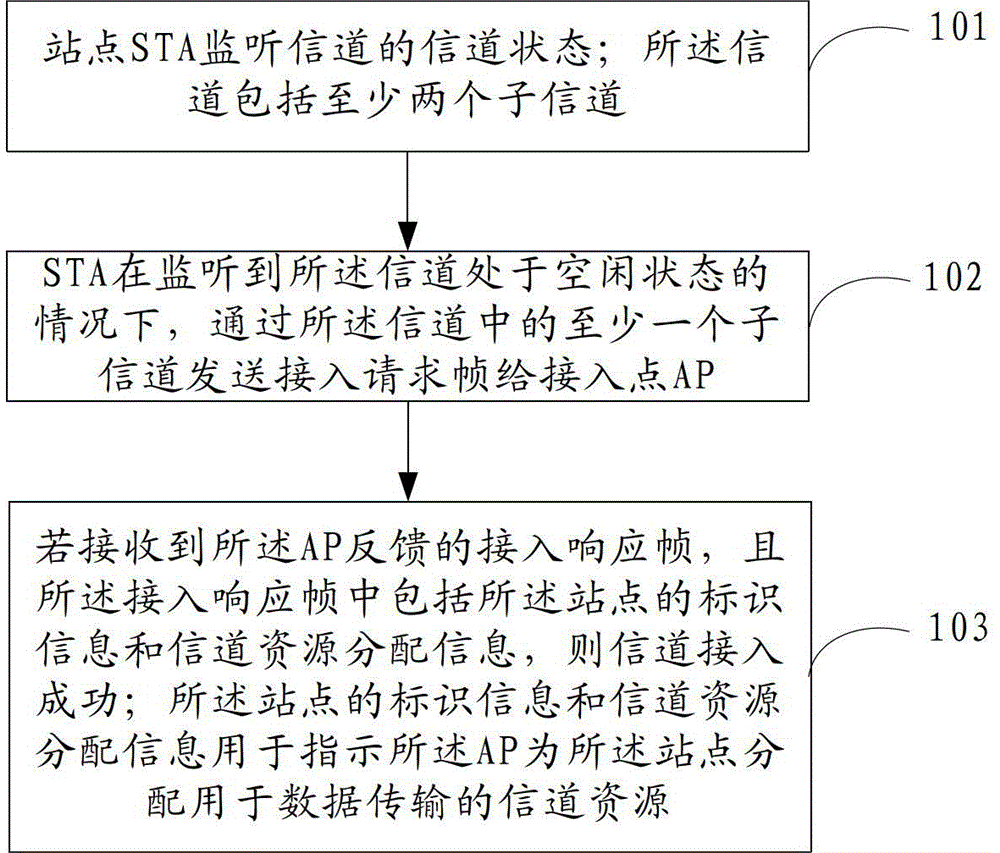
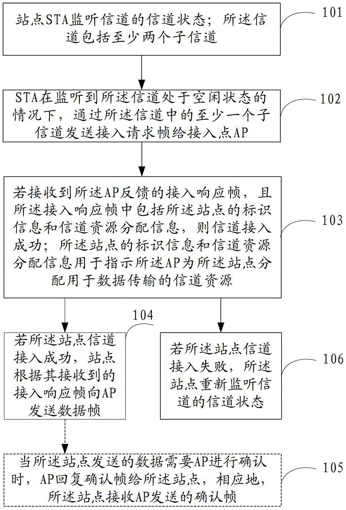
[0129] Step 501, 8 STAs monitor the busy / idle status of the channel. If the idle time of the channel reaches the DIFS time, go to step 502, otherwise stay at step 501.

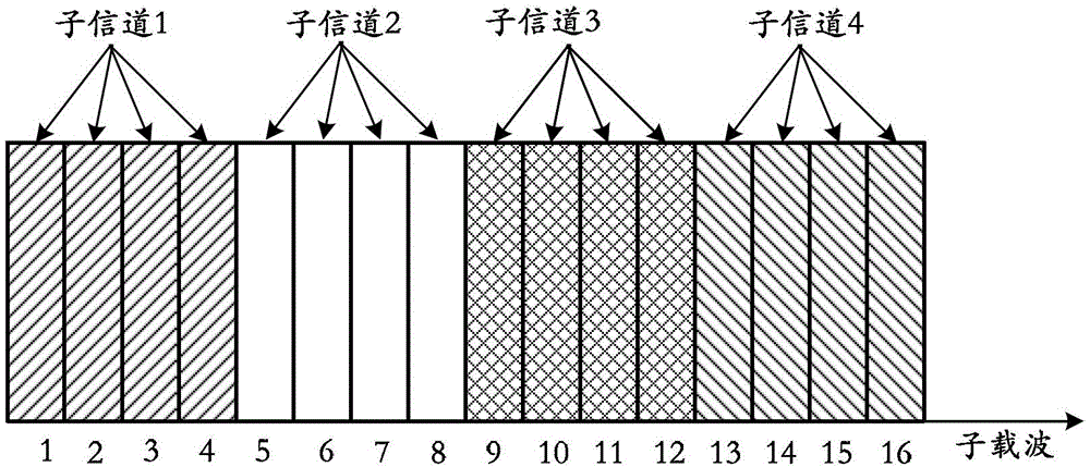
[0130] Specifically, the channel is divided into 4 sub-channels, and the 4 sub-channels are mutually orthogonal. When the energy signal strength in the channel is greater than or equal to the preset threshold, the channel is considered to be in a busy state; when the energy signal strength in the channel is less than the preset threshold, the channel is considered to be in an idle state.

[0131] Step 502 , assuming that STA1 , STA2 , STA3 and STA4 all select the backoff time to be 2T, and the backoff time selected by STA5 , STA6 , STA7 and STA8 are all greater than 2T, perform a backoff process.

[0132] Step 503. After 2T time, the STA with a backoff time of 2T randomly selects a subchannel to send an RTS frame to the AP, and then proceeds to step 504; the STA with a backoff time greater than 2T proceeds to...

Embodiment 2

[0141] This embodiment provides a method for data transmission when channel access is successful, including: steps 501-504 in Embodiment 1, which are steps 601-604 in this embodiment, which will not be repeated here. Such as Figure 6 As shown, this embodiment also includes:

[0142] Step 605, STA1 and STA2 according to the received G-CTS frame, after waiting for the channel to be free for SIFS time, STA1 sends DATA1 frame to AP on sub-channel 1 and sub-channel 2, STA2 sends DATA2 frame on sub-channel 3 and sub-channel 4 to AP. Correspondingly, the AP receives the DATA1 frame sent by STA1 and the DATA2 frame sent by STA2.

[0143] Specifically, STA1, STA2, STA3, and STA4 receive the G-CTS frame sent by the AP through the channel. Since the G-CTS frame only contains the channel resource allocation information for STA1 and STA2, it does not contain the channel resource allocation information for STA3 and STA4. Resource allocation information, so after STA1 and STA2 wait for t...

Embodiment 3

[0150] Next, the present invention also provides another specific embodiment, which describes in detail the method for data transmission when the channel access is successful.

[0151] In this embodiment, steps 501-504 in Embodiment 1 are included, which are steps 701-704 in this embodiment, which will not be repeated here. Such as Figure 7 As shown, this embodiment also includes:

[0152] Step 705. According to the received G-CTS frame, STA1 and STA2 send the DATA1 frame to the AP on the entire channel after STA1 waits for the channel to be idle for SIFS time, and STA2 waits for the channel to be idle for SIFS time before sending the DATA2 frame on the entire channel to AP. Correspondingly, the AP receives the DATA1 frame sent by STA1 and the DATA2 frame sent by STA2, such as Figure 7 shown in .

[0153] If the data sent by STA1 and STA2 (for example: broadcast frame, multicast frame) does not require the AP to confirm, then the AP only needs to receive the data sent by...


PUM


Abstract

Disclosed in the present invention are a method, an apparatus and a system for channel access. Through simplifying the monitoring process for an STA (station), the satisfaction of time synchronization when a plurality of STAs access channels can be supported so as to avoid signal interference between adjacent frequency bands. The method comprises: monitoring the channel state of a channel by a station (STA), the channel including at least two sub-channels; in the case of monitoring the channel at an idle state, sending an access request frame to an access point (AP) through at least one sub-channel of the channel; if receiving an access response frame fed back by the AP, and the access response frame including identification information and channel resource allocation information of the station, then the channel access is successful; and the identification information and channel resource allocation information of the station is used to indicate that the AP allocates channel resources for data transmission to the station.

Description

technical field [0001] The present invention relates to the technical field of wireless communication, in particular to a channel access method, device and system. Background technique [0002] For the data transmission process of the wireless local area network, the IEEE802.11 agreement has carried on the detailed regulation to it. In a wireless local area network, it generally includes an access point (AP, Access Point) and multiple stations (STA, Station). If the STA has data to send, it must first send the data to the AP, and then be forwarded by the AP. to other network nodes. Therefore, when multiple STAs in a wireless local area network have data to be sent at the same time, they will inevitably compete for channel resources. [0003] The IEEE802.11 protocol stipulates that all STAs use the same channel to send access request frames to compete for channel resources. Therefore, in a wireless local area network, when multiple STAs send access request frames at the sam...

Claims


Application Information

Patent Timeline
Patent Type & Authority Applications(China)
IPC IPC(8): H04W72/04H04W74/08
CPCH04W74/0808H04L5/003H04W74/04
Inventor 李波屈桥李云波伍天宇
Owner HUAWEI TECH CO LTD
Why Eureka
Try Eureka