Sunflower harvester

A harvester and sunflower technology, applied in the field of agricultural machinery, can solve the problems of grain loss, dirty threshing, broken sunflower seeds, etc., and achieve the effects of easy processing and production, simple and clear structure, and high harvesting efficiency

Inactive Publication Date: 2015-03-04
许开军
View PDF5 Cites 3 Cited by
  • Summary
  • Abstract
  • Description
  • Claims
  • Application Information

AI Technical Summary

Problems solved by technology

[0002] Wheat and corn have now achieved mechanical combined harvesting, and the seeds are directly obtained from the fields. The large sunflower growers who have thousands of acres of sunflowers are also eager to manufacture a combined sunflower harvesting equipment like a wheat combine harvester to solve the problem of relying on Manpower is labor-intensive and time-consuming, so some people use wheat or corn combine harvesters to modify them to harvest sunflowers. However, when wheat threshing machines are used for threshing sunflower heads, the shape of wheat or corn crops is quite different from that of sunflower heads. The threshing effect is not ideal, and the sunflower seeds are broken or threshed. Therefore, the sunflower harvester modified from the wheat / corn combine harvester has no major improvement in the threshing device, which will cause seed loss. In addition, the sunflower heads are very wet, large and The stalks are sticky to a certain extent, and it is not suitable to be cleaned by wind blowing. Also, due to the different heights of the sunflower pans, the existing sunflower cutting part can only cut the sunflower stalks at a certain height from the ground, which is too high for the sunflower pans. The lower sunflower plate cannot be cut, and the length of the pole is too low, which will increase the workload of threshing and screening in the next step, and the sunflower seeds contain a lot of debris

Method used


Image

  • Sunflower harvester
  • Sunflower harvester
  • Sunflower harvester

Examples


Embodiment Construction

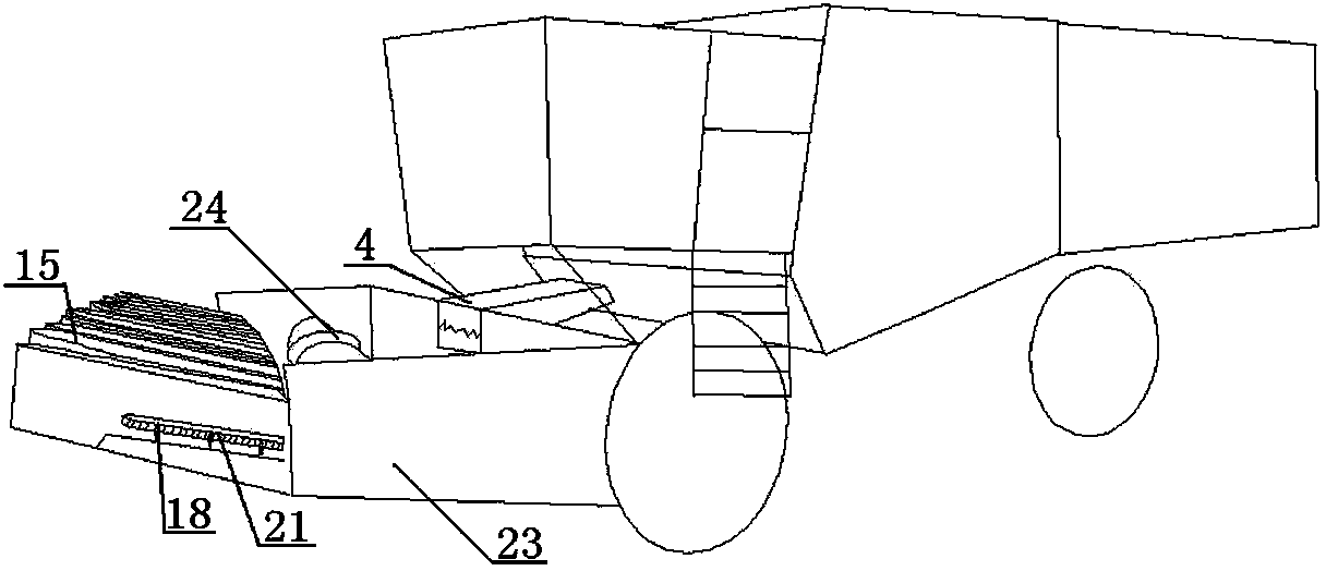
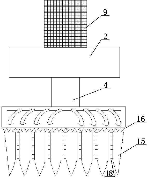
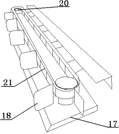
[0020] As shown in the figure, a sunflower harvester includes a row divider 15, a cutting tooth knife 16, and the cutting tooth knife 16 is adjacent to the rear end of the spreader 15, and the cutting tooth knife 16 reciprocates to cut off the stalk, making it a reciprocating part The cutter structure on the wheat harvester or electric razor can be used. The branching device 15 is supported by the bracket 17. The front end of the branching device 15 is an arc-shaped streamlined structure similar to the front end of a ship, which is convenient for the stalks to enter the row. 15 stretches out the sunflower stalk dividing plate 18, and the sunflower stalk dividing plate 18 is fixed on the rotating device inside the row divider 15, and forms the grid that gap can accommodate vertical sunflower stalk between the adjacent sunflower stalk dividing plate 18 , along with the advancement of the sunflower harvester, the sunflower stalks are constantly gathered in the grid, and the sunflo...


PUM


Abstract

The invention provides a sunflower harvester which comprises a sunflower-row cutting part, a transferring part, a threshing part and a screening storage part, wherein sunflower stalks are cut off by a serrated knife to obtain sunflower heads; the sunflower heads are transferred to the threshing part from the transferring part for threshing; the sunflower heads are rubbed and pressed by rotating an inner cylinder; the threshed grains are screened by a dual-layer vibrating screen and are centralized and elevated to a grain storage bin in a spiral conveying manner. The sunflower harvester has the benefits that only the sunflower heads are cut; the stalks on the sunflower heads are extremely short and convenience is brought to subsequent threshing and screening; the grains and the heads are thoroughly separated; the sunflower heads are great in broken piece; the grains and the heads are easily separated; sunflower seeds are prevented from being broken; when the sunflower harvester and the sunflower reaper are combined, the sunflower seeds with fewer impurities can be directly obtained from the field; the threshing, screening and storing for a stock bin can be realized; the stock bin is great in size and high in capacity, so non-stop harvesting for a longer time can be realized.

Description

technical field [0001] The invention belongs to the field of agricultural machinery, and relates to a sunflower harvesting machine, in particular to an integrated mechanized device for sunflower harvesting, threshing, screening and temporary storage. Background technique [0002] Wheat and corn have now achieved mechanical combined harvesting, and the seeds are directly obtained from the fields. The large sunflower growers who have thousands of acres of sunflowers are also eager to manufacture a combined sunflower harvesting equipment like a wheat combine harvester to solve the problem of relying on Manpower is labor-intensive and time-consuming, so some people use wheat or corn combine harvesters to modify them to harvest sunflowers. However, when wheat threshing machines are used for threshing sunflower heads, the shape of wheat or corn crops is quite different from that of sunflower heads. The threshing effect is not ideal, and the sunflower seeds are broken or threshed. ...

Claims


Application Information

Patent Timeline
Patent Type & Authority Applications(China)
IPC IPC(8): A01D41/02
Inventor 许开军
Owner 许开军
Why Eureka
Try Eureka