
Special-shaped pipe sawing method

A special-shaped pipe and sawing technology, applied in the field of pipe processing, can solve the problems of difficult shaping, deviation, and poor sawing effect.

Active Publication Date: 2015-03-04
NINGBO SIMING AUTOMOBILE TECH
View PDF5 Cites 2 Cited by
  • Summary
  • Abstract
  • Description
  • Claims
  • Application Information

AI Technical Summary

Problems solved by technology

[0002] In the field of pipe fittings processing, for sawing of straight pipes, the straight pipe clamp is generally used to clamp the straight pipe, and then sawed, while for the sawing of special-shaped pipes, the special-shaped pipe is generally clamped by the special-shaped pipe clamp, and then sawed In this method, due to the irregular shape of the special-shaped tube, in order to be able to clamp the special-shaped tube, a cavity slightly larger than the shape of the special-shaped tube is generally provided in the special-shaped tube clamp to facilitate the clamping of the special-shaped tube, but due to both There is still a gap between them, so the special-shaped tube will still be loose on the fixture, so when sawing, the sawing effect is often not good, and deviations will occur, and finally it still needs to be shaped, the operation is troublesome, and the sawing effect is not good
Once there is a deviation during the sawing process, it will be very difficult to shape the final product, which will often result in a low pass rate of the product

Method used


Image

  • Special-shaped pipe sawing method
  • Special-shaped pipe sawing method

Examples


Embodiment Construction

[0017] Below in conjunction with accompanying drawing and specific embodiment the present invention will be described in further detail:

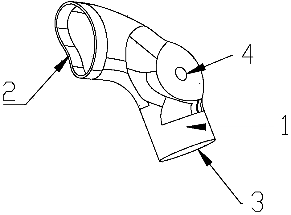
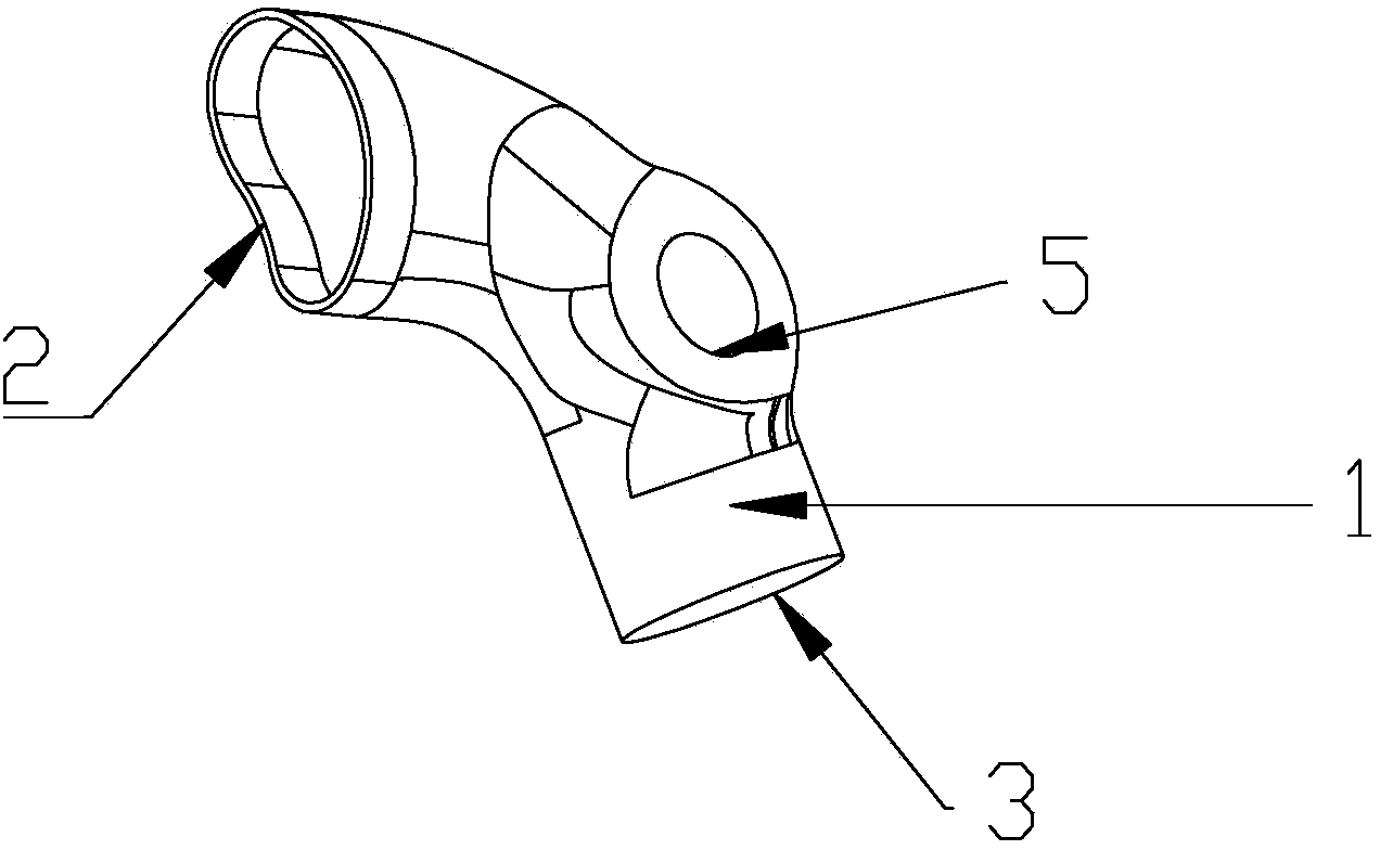
[0018] Such as figure 1 figure 2 As shown, the invention provides a special-shaped pipe sawing method, which comprises the following steps:

[0019] a. Mill a process hole 4 at the pre-punched position of the special-shaped pipe in the pipe fitting to be sawed;

[0020] b. Put part of the pipe fittings that are special-shaped pipes into the clamp and clamp them, and saw the special-shaped pipe fittings from the pipe fittings;

[0021] c. Put the special-shaped pipe sawn in the previous step into the first special-shaped pipe fixture. The first special-shaped pipe fixture is provided with a first through hole corresponding to the position of the process hole on the special-shaped pipe, and the bolt passes through the process. The hole and the first through hole secure the special-shaped pipe in the first special-shaped pipe fixture, and ...


PUM


Abstract

The invention provides a special-shaped pipe sawing method. The special-shaped pipe sawing method comprises the following steps: milling a process hole in a pre-punching position of a special-shaped pipe in a pipe fitting to be sawed; putting the pipe fitting which has part of the special-shaped pipe into a clamp to be clamped; sawing the special-shaped pipe from the pipe fitting; putting the special-shaped pipe sawed in the last step into a first special-shaped pipe clamp; sawing a first pipe opening of the special-shaped pipe; reversely putting the special-shaped pipe sawed in the last step into a second special-shaped pipe clamp; sawing a second pipe opening of the special-shaped pipe; removing burrs of the two pipe openings by a grinding machine; forming a connection hole of the special-shaped pipe; reshaping, removing the burrs and washing to finish the method, wherein the hole diameter of the connection hole is larger than that of the process hole. When the method is used for sawing, the special-shaped pipe does not shake and the sawing effect is better; the position of the process hole is formed and needs to be expanded to form the connection hole in subsequent machining so that the whole shape of the special-shaped pipe is completely not influenced; the special-shaped pipe sawing method is simple and convenient and has better machining effect.

Description

technical field [0001] The invention relates to the field of pipe material processing, in particular to a sawing method for special-shaped pipes with connecting holes. Background technique [0002] In the field of pipe fittings processing, for sawing of straight pipes, the straight pipe clamp is generally used to clamp the straight pipe, and then sawed, while for the sawing of special-shaped pipes, the special-shaped pipe is generally clamped by the special-shaped pipe clamp, and then sawed In this method, due to the irregular shape of the special-shaped tube, in order to be able to clamp the special-shaped tube, a cavity slightly larger than the shape of the special-shaped tube is generally provided in the special-shaped tube clamp to facilitate the clamping of the special-shaped tube, but due to both There is still a gap between them, so the special-shaped pipe will still loosen on the fixture, so when sawing, the sawing effect is often not good, and deviations will occur,...

Claims


Application Information

Patent Timeline
IPC IPC(8): B23P15/00B23Q3/00
CPCB23P15/00B23Q3/00B23Q2703/10
Inventor 吴江汪涌涛
Owner NINGBO SIMING AUTOMOBILE TECH
Learn More