
Handheld fiber wire laying device

A fiber and silk laying technology, which is applied in the field of hand-held fiber laying devices, can solve the problems of large-scale production that is not suitable for modernization, low material utilization rate, and low efficiency of manual laying, so as to achieve good laying effect and save energy. manpower, efficiency improvement effect

Inactive Publication Date: 2015-03-04
WUHAN UNIV OF TECH
View PDF8 Cites 8 Cited by
  • Summary
  • Abstract
  • Description
  • Claims
  • Application Information

AI Technical Summary

Problems solved by technology

[0003] At present, domestic composite material forming is still dominated by manual laying, but the research on fiber laying technology at home and abroad is concentrated on automatic laying forming equipment and automatic forming software, most of which are automatic laying manipulators and machine tools , there are few studies on hand-held filament placement devices
[0004] In order to overcome the problems of low efficiency of manual layer laying, low utilization rate of materials, and unsuitability for modern large-scale production, a hand-held fiber filament laying device is urgently needed. This device must be able to improve production efficiency and facilitate workers to complete flexibly and effortlessly. The work of laying fibers must also be able to accurately complete the laying of special-shaped mold cores

Method used


Image

  • Handheld fiber wire laying device
  • Handheld fiber wire laying device
  • Handheld fiber wire laying device

Examples


Embodiment Construction

[0035] In order to make the object, technical solution and advantages of the present invention clearer, the present invention will be further described in detail below in conjunction with the accompanying drawings and embodiments. It should be understood that the specific embodiments described here are only used to explain the present invention, not to limit the present invention.

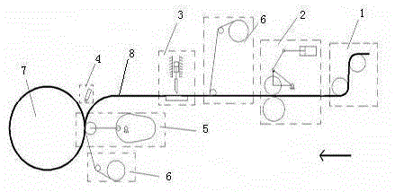
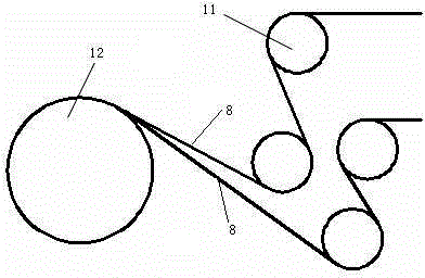
[0036] Such as figure 1 As shown, the laying head includes a wire guide module 1, a feeding module 2, a cutting module 3, a heating module 4, a pressure head module 5 and a backing paper recovery module 6; the wire guide module 1 separates the fiber prepreg 8 from the belt The disc is guided to the laying head, and the fiber prepreg tape passes through the re-feeding module 2, the cutting module 3, the heating module 4 and the pressure head module 5 on the laying head, and finally lays on the core mold 7; the laying head There are two backing paper recovery modules 6 in the middle, the first one i...


PUM


Abstract

The invention relates to a handheld fiber laying device. The device comprises a mechanical arm and a laying head, wherein the mechanical arm is fixed on the ground or on a trolley, and the laying head is fixed at the front end of the mechanical arm; the mechanical arm comprises a fixed column, a rotating column, a control box, a swinging arm, a main arm, a small arm, a suspension arm, a cylinder and a pneumatic balance system; and the laying head comprises a wire guiding module, a re-delivering module, a cutting module, a pressure head module, a lining paper recycling module and a heating module. The mechanical arm disclosed by the invention enables a worker to push the workpiece and complete the laying work by using a very weak force, and the mechanical arm can automatically maintain a state of equilibrium in any position and any condition; the laying head disclosed by the invention can laying a plurality of narrow fiber prepreg tapes at one time and can complete the functions of wire guiding, conveying, lining paper recycling, shearing, heating and laying, and the laying head is not only suitable for a mandrel with a simple structure of a cylinder, but also is suitable for a mandrel with a special structure of a cone or a latticed shape. The handheld fiber laying device has the advantages of simplicity in operation, less manpower, high efficiency, and good laying effect.

Description

technical field [0001] The invention relates to a fiber filament laying device, in particular to a hand-held fiber filament laying device. Background technique [0002] Fiber placement technology is one of the most productive composite molding technologies. This new molding technology was originally used mainly in the aerospace industry. With the continuous development of fiber placement technology, this technology is now widely used in various industries. [0003] At present, domestic composite material forming is still dominated by manual laying, but the research on fiber laying technology at home and abroad is concentrated on automatic laying forming equipment and automatic forming software, most of which are automatic laying manipulators and machine tools , there are few studies on hand-held filament placement devices. [0004] In order to overcome the problems of low efficiency of manual layer laying, low material utilization rate, and unsuitability for modern large-s...

Claims


Application Information

Patent Timeline
IPC IPC(8): B29C70/38
CPCB29C70/382
Inventor 田会方吴迎峰李力
Owner WUHAN UNIV OF TECH
Learn More