
Warp beam dyeing system and warp beam dyeing method

A beam dyeing and beam beam technology, applied in the field of yarn dyeing, can solve the problems of high consumption of chemical auxiliaries, difficult to meet production emission requirements, etc., and achieve the effect of reducing energy consumption and reducing the dyeing bath ratio of beam beam.

Inactive Publication Date: 2015-03-04
GUANGDONG ESQUEL TEXTILES CO LTD
View PDF6 Cites 2 Cited by
  • Summary
  • Abstract
  • Description
  • Claims
  • Application Information

AI Technical Summary

Problems solved by technology

[0003] The traditional warp beam dyeing method has a high consumption of water, steam, and chemical additives due to the limitation of its own dyeing method. With the improvement of social and social environmental protection awareness, energy saving, emission reduction and friendly environment have gradually become the development trend of the industry. With the increasing emphasis on high energy consumption and high pollution industries, the traditional warp beam dyeing method is facing unprecedented cost and environmental pressure, and it is difficult to adapt to the new production emission requirements. A new method and technology is urgently needed to reduce the warp beam dyeing energy. Consumption and Wastewater Discharge

Method used


Image

  • Warp beam dyeing system and warp beam dyeing method
  • Warp beam dyeing system and warp beam dyeing method
  • Warp beam dyeing system and warp beam dyeing method

Examples


Embodiment Construction

[0027] In order to facilitate the understanding of the present invention, the present invention will be described more fully below with reference to the associated drawings. Preferred embodiments of the invention are shown in the accompanying drawings. However, the present invention can be embodied in many different forms and is not limited to the embodiments described herein. On the contrary, these embodiments are provided to make the understanding of the disclosure of the present invention more thorough and comprehensive.

[0028] It should be noted that when an element is referred to as being “fixed” to another element, it can be directly on the other element or there can also be an intervening element. When an element is referred to as being "connected to" another element, it can be directly connected to the other element or intervening elements may also be present.

[0029] Unless otherwise defined, all technical and scientific terms used herein have the same meaning as...


PUM

PropertyMeasurementUnit
Diameteraaaaaaaaaa
Axial lengthaaaaaaaaaa

Abstract

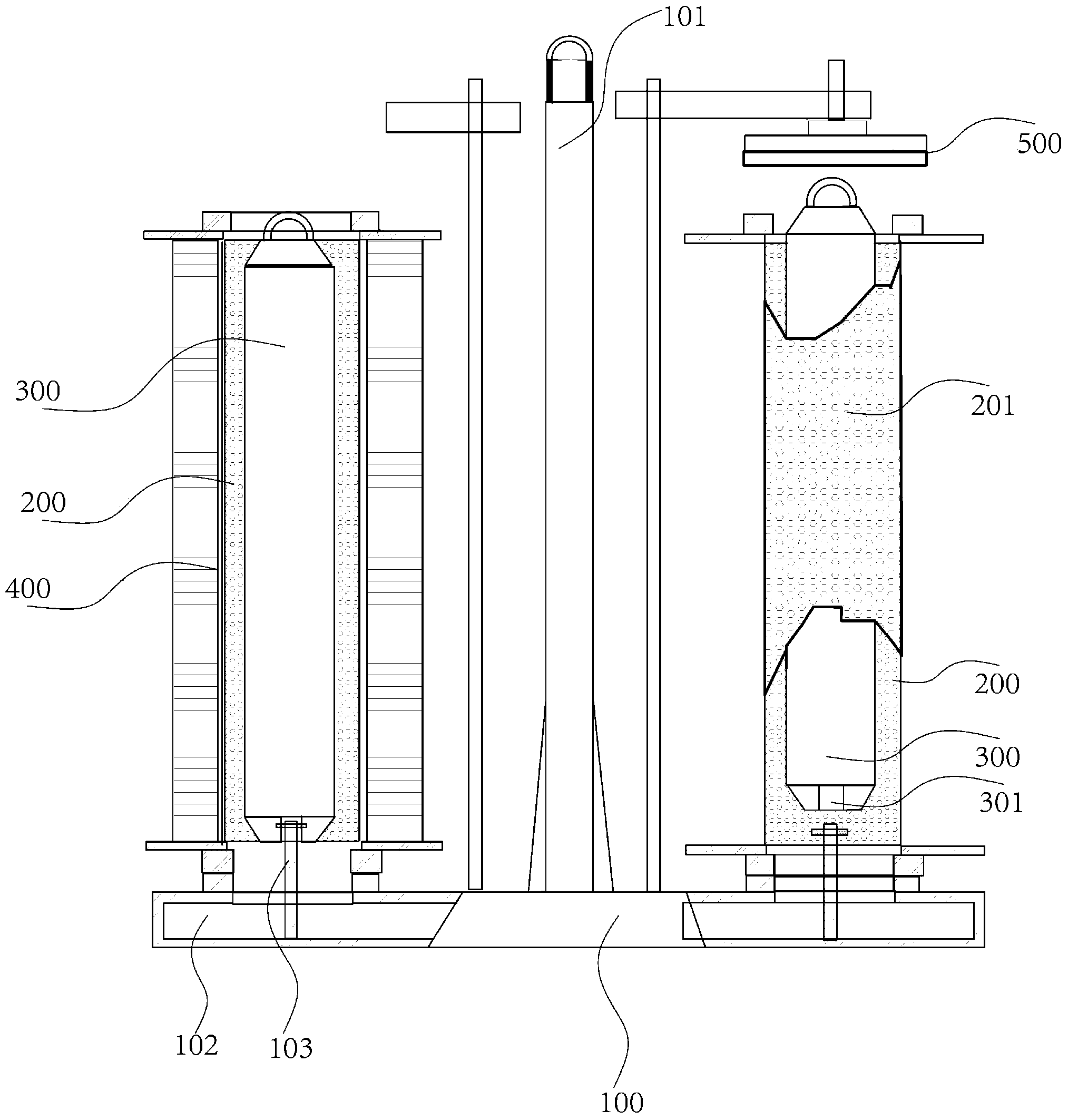
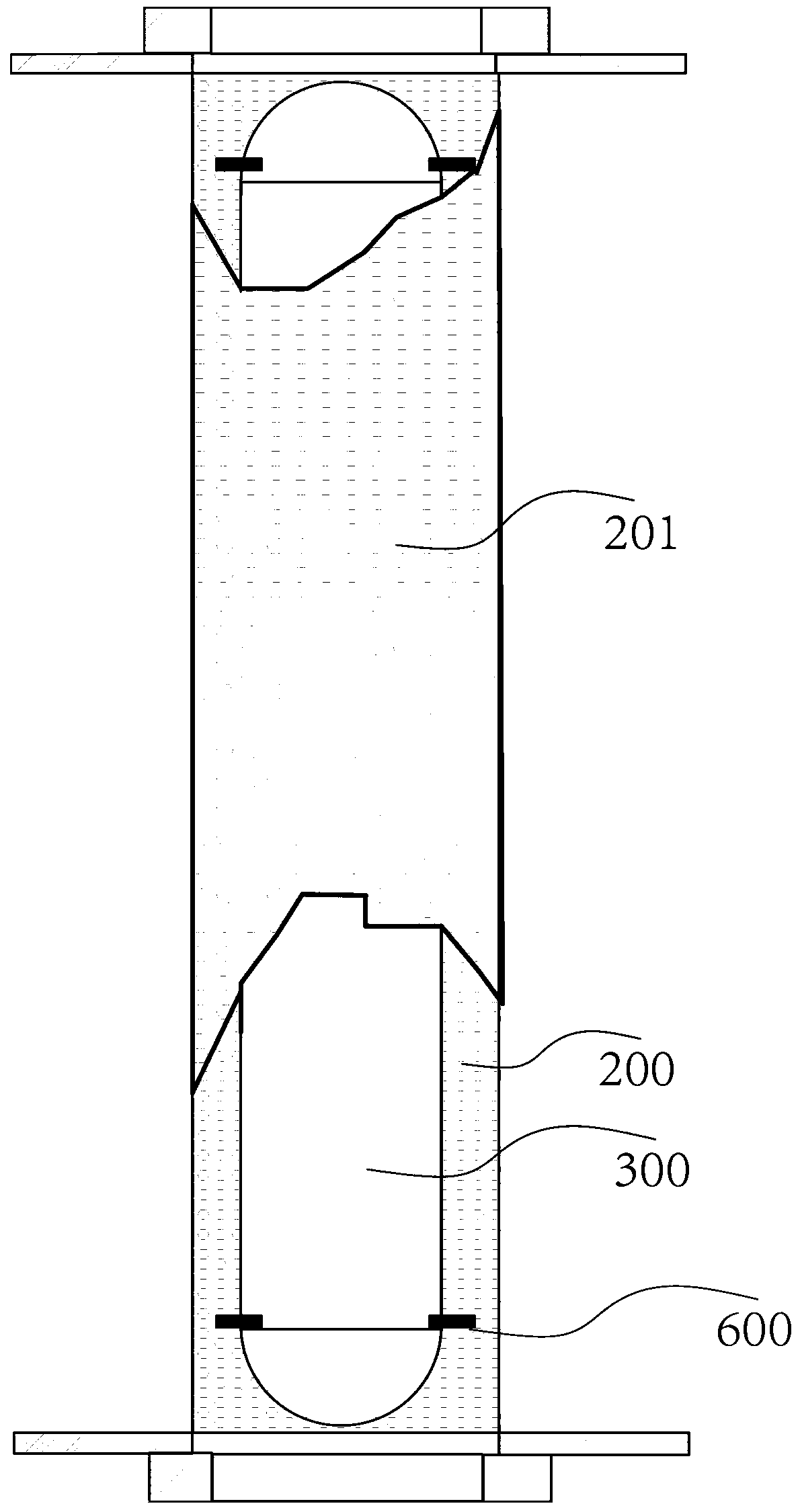
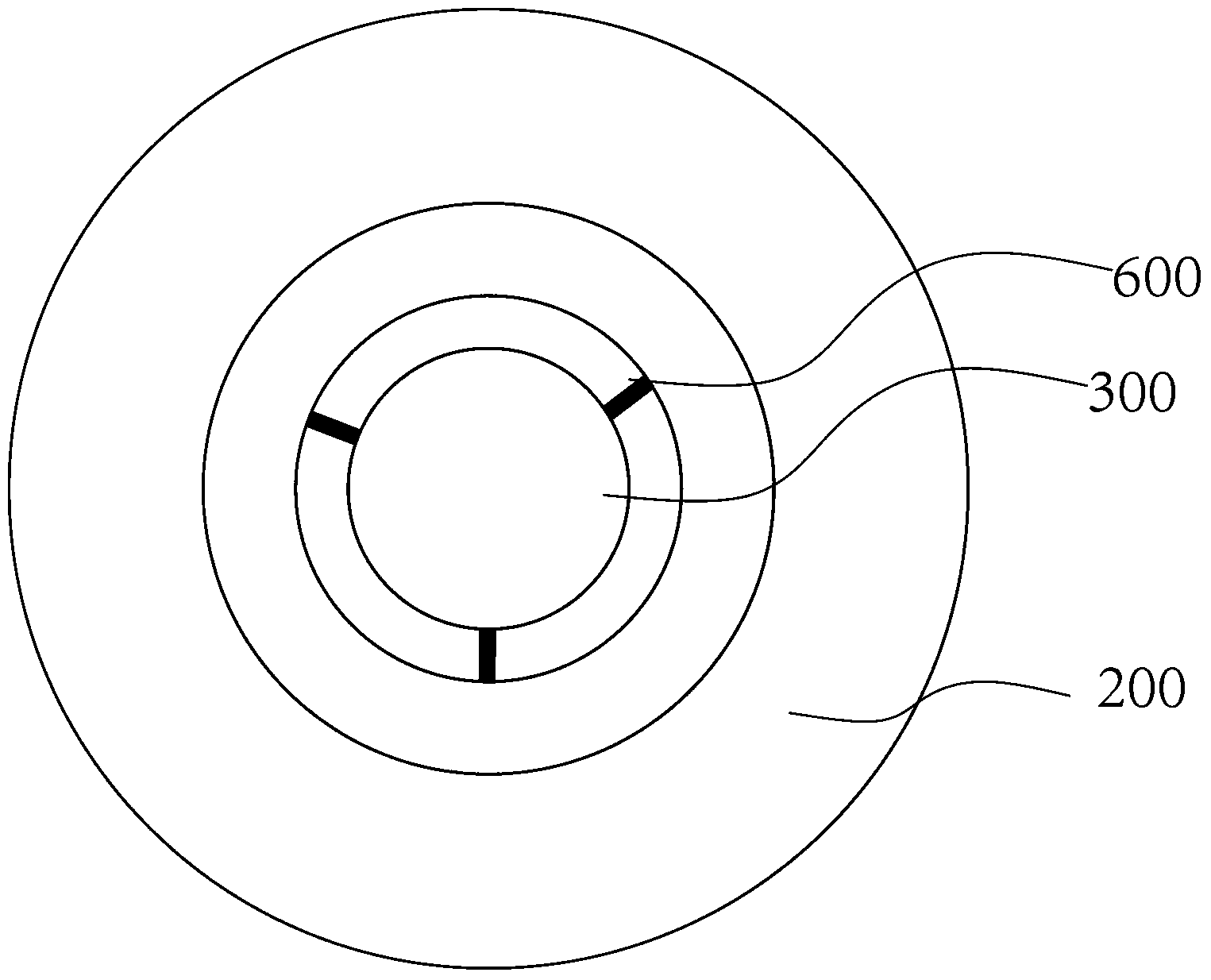
The invention discloses a warp beam dyeing system and a warp beam dyeing method. The warp beam dyeing system comprises a dyeing vat, a pump, a creel, a plurality of beams and water drain barrels, wherein the water drain barrels are sealed, the creel is arranged in the dyeing vat, the plurality of beams are connected onto the creel, the beams are hollow shafts, chambers of the beams are formed inside the hollow shafts, a plurality of through holes for a dyeing liquid to pass are formed in side walls of the beams, and the water drain barrels are arranged in the chambers of the beams. By the aid of the warp beam dyeing system, water consumption, steam consumption and chemical material consumption can be reduced.

Description

technical field [0001] The invention relates to the field of yarn dyeing, in particular to a warp beam dyeing system and a dyeing method thereof. Background technique [0002] The printing and dyeing industry is a traditional high-pollution industry in the manufacturing industry. Yarn dyeing, as an important part of preventing printing and dyeing, is also a high-energy and water-consuming industry. Yarn dyeing is currently divided into skein dyeing, cheese dyeing, warp beam dyeing, etc. The method of cheese dyeing and warp beam dyeing is similar. They are all in the dyeing vat, and the liquid flow is driven by a pump to penetrate the whole cheese and warp beam. Make the dyeing solution achieve the purpose of dyeing the yarn. During the production process, the yarn needs to be half-immersed or fully immersed in the dyeing solution, so a large amount of water is required for dyeing and washing, so the water consumption, sewage discharge and energy use are relatively large. ...

Claims


Application Information

Patent Timeline
IPC IPC(8): D06B3/04D06B23/00
CPCD06B3/09D06B23/20D06B2700/06
Inventor 张三强何韵湘安志轩区树横
Owner GUANGDONG ESQUEL TEXTILES CO LTD
Learn More