Air conditioner oiling device

An oil injection device and air-conditioning technology, which is applied in the direction of liquid variable displacement machinery, variable displacement pump components, machines/engines, etc., can solve the problems of low efficiency, time-consuming and laborious injection, etc., and achieve convenient operation, high degree of automation, and structure simple effect

Inactive Publication Date: 2015-03-04
GREE ELECTRIC APPLIANCES INC
View PDF8 Cites 9 Cited by
  • Summary
  • Abstract
  • Description
  • Claims
  • Application Information

AI Technical Summary

Problems solved by technology

[0002] At present, the company and after-sales companies need to add lubricating oil to the air conditioners of the closed-loop system, and the existing technology is to use the oil gun to complete the system itself. The system itself needs a vacuum, and the oil gun has a disadvantage. When refueling, the air It is easy to inject into the vacuum system with the refrigerated oil, and when the oil is injected, the system itself has a certain pressure, and it is difficult to inject the oil into the system by manual operation. The operation method is primitive, time-consuming, laborious, and inefficient.

Method used


Image

  • Air conditioner oiling device

Examples


Embodiment 1

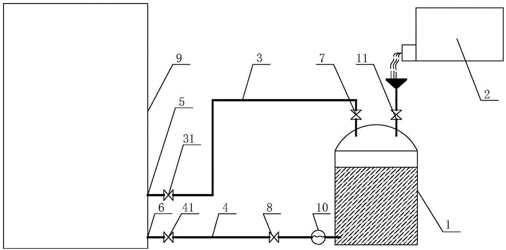
[0022] An air-conditioning oil injection device provided by the present invention has a structure such as figure 1 As shown, it includes an oil filling tank 1, the oil filling tank 1 is connected to the oil tank 2 through an oil pipe, and an oil filling valve 11 is arranged on the oil pipe connecting the oil filling tank 1 and the oil tank 2, and the oil filling valve 11 is preferably a shut-off valve. The oil filling tank 1 is connected with the exhaust port end 5 of the air-conditioning compressor 9 through the first connecting pipe 3, the oil filling tank 1 is connected with the air inlet end 6 of the compressor 9 through the second connecting pipe 4, and the first connecting pipe 3 And the tail end of the oil pipe is positioned at the top of the oil filling tank 1, the tail end of the second connecting pipe 4 is positioned at the bottom of the oil filling tank 1, and the first connecting pipe 3 and the second connecting pipe 4 can adopt leather tubes or flexible pipes. The...

Embodiment 2

[0031] This embodiment provides another air conditioner oil injection device, the structure of which is basically the same as that of the air conditioner oil injection device described in Embodiment 1, which includes an oil injection tank connected to the oil tank through an oil pipe, The tank is connected to the exhaust port of the air conditioner compressor through the first connecting pipe, and the oil filling tank is connected to the air inlet end of the compressor through the second connecting pipe. The first connecting pipe is provided with a booster valve, and the second connecting pipe There is an oil discharge valve on it.

[0032] The difference is that the air-conditioning oil injection device of this embodiment also includes a controller, which is respectively connected to the boost valve, the oil discharge valve and the oil injection valve, and the pressure boost valve, the oil discharge valve and the oil injection valve are all solenoid valves. In this embodiment...


PUM


Abstract

The invention discloses an air conditioner oiling device, and belongs to the technical field of air conditioners. The air conditioner oiling device is designed for solving the problems that an existing air conditioner oiling device wastes time and labor in oiling, is low in oiling efficiency and the like. The air conditioner oiling device comprises an oiling tank, wherein the oiling tank is connected with an oil tank through an oil pipe, the oiling tank is connected with an exhaust port end of an air condition compressor through a first connection pipe, the oiling tank is connected with an air inlet end of the air condition compressor through a second connection pipe, a pressure increasing valve is arranged on the first connection pipe, and an oil discharge valve is arranged on the second connection pipe. The air conditioner oiling device uses differential pressure to achieve an oiling mode of automatically injecting lubricating oil into the air condition compressor, is simple in structure and convenient to operate, improves oiling efficiency, and saves time and labor.

Description

technical field [0001] The invention belongs to the technical field of air conditioners, in particular to an air conditioner oil injection device. Background technique [0002] At present, the company and after-sales companies need to add lubricating oil to the air conditioners of the closed-loop system, and the existing technology is to use the oil gun to complete the system itself. The system itself needs a vacuum, and the oil gun has a disadvantage. When refueling, the air It is easy to inject into the vacuum system with the refrigerated oil, and when the oil is injected, the system itself has a certain pressure, and it is difficult to inject the oil into the system by manual operation. The operation method is primitive, time-consuming, laborious, and inefficient. Contents of the invention [0003] The object of the present invention is to propose an air conditioner oiling device with simple structure, convenient operation, automatic oiling, time saving and labor saving...

Claims


Application Information

Patent Timeline
Patent Type & Authority Applications(China)
IPC IPC(8): F04B39/02F04B39/00
Inventor 刘方这赖海龙
Owner GREE ELECTRIC APPLIANCES INC
Why Eureka
Try Eureka