Unlock instant, AI-driven research and patent intelligence for your innovation.

Exhaust treatment system having an scr with a center inlet

A technology of exhaust treatment and exhaust flow, which is applied in the field of vehicles on the other hand, can solve problems such as hindering access to other components, contacting other objects, and restricting the operator's field of vision.

Active Publication Date: 2015-03-04
凯斯纽荷兰(中国)管理有限公司
View PDF6 Cites 1 Cited by
  • Summary
  • Abstract
  • Description
  • Claims
  • Application Information

AI Technical Summary

Problems solved by technology

These components must operate efficiently but must not restrict the operator's field of vision
Furthermore, such exhaust treatment systems cannot extend outwardly away from the vehicle, otherwise they would obstruct access to other components or they would inadvertently come into contact with other objects during operation

Method used


Image

  • Exhaust treatment system having an scr with a center inlet
  • Exhaust treatment system having an scr with a center inlet

Examples


Embodiment Construction

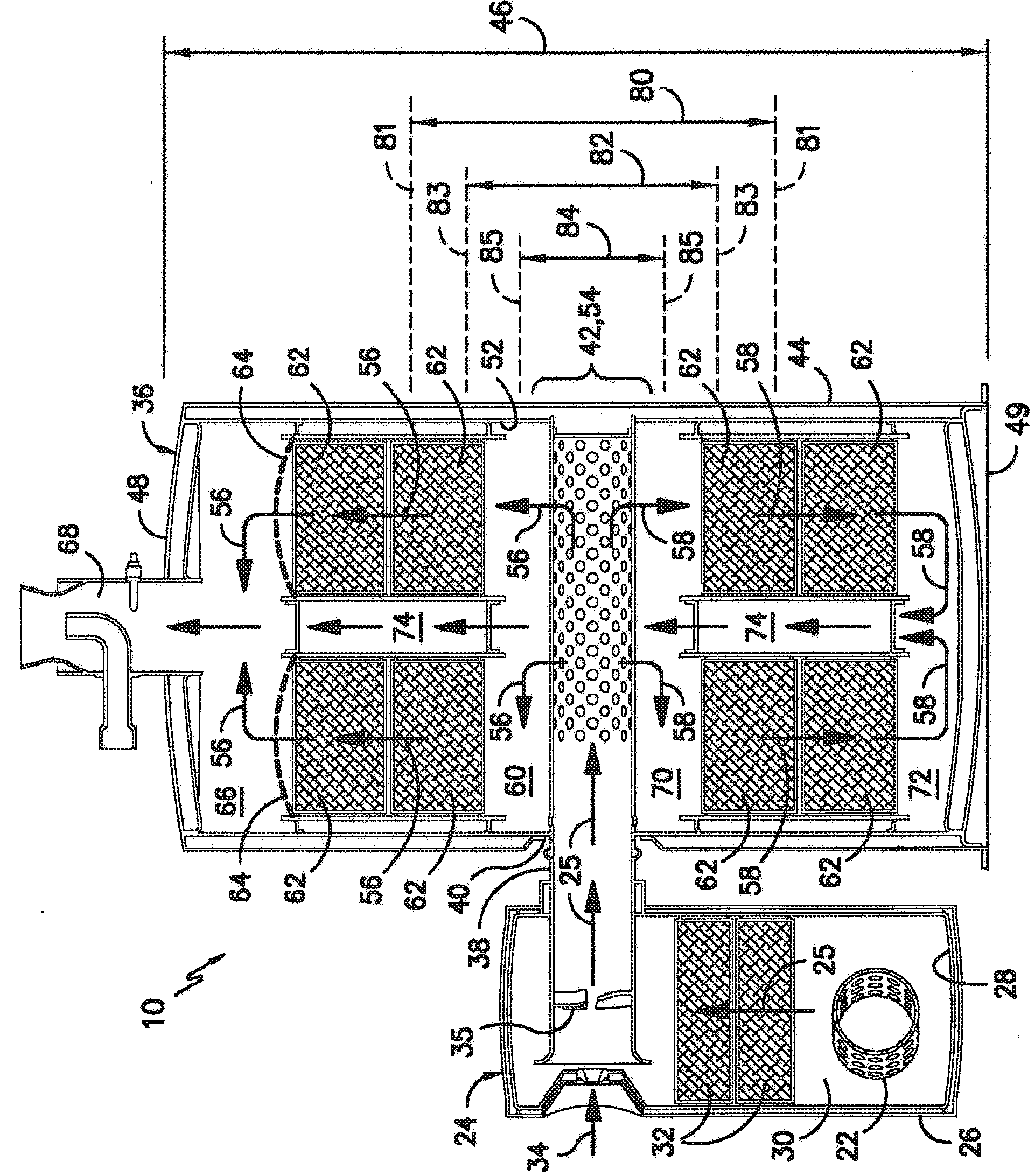
[0010] figure 1 Exhaust treatment system 10 of a work vehicle (not shown) is shown including an SCR with a central inlet. The work vehicle includes an engine 12 which may include a turbocharger 14 . Exhaust conduit 16 desirably, but not limitedly, connects at first end 18 to turbocharger 14 of engine 12 . Alternatively, it will be appreciated that exhaust conduit 16 may be connected to other outlets associated with engine 12 to receive exhaust flow. Exhaust conduit 16 includes a second end 20 that desirably connects to an inlet 22 of a DOC 24 . It should be appreciated that exhaust flow 25 moves from turbocharger 14 through exhaust conduit 16 and into DOC 24 . The DOC 24 includes a housing 26, which may be cylindrical in shape, although other configurations may equally operate.

[0011] Such as figure 2 As shown in , housing 26 includes an interior surface 28 that defines an interior compartment 30 . Exhaust flow 25 enters an interior compartment 30 of housing 26 and id...


PUM


Abstract

An exhaust treatment system for a work vehicle, which has an exhaust conduit transmitting an exhaust flow from an engine and to a DOC system, is disclosed. The DOC system has a reductant introduced and mixed into the exhaust flow, and a DOC conduit connects the DOC to a center inlet of an SCR. The SCR includes at least two exhaust chambers. When the exhaust flow enters the SCR at the center inlet, the exhaust flow enters a central chamber where it is split into at least two separate exhaust flows which are moved in at least two different directions away from each other. Each separate exhaust flow is moved through a separate exhaust chamber and substrate. A conduit moves at least one of the separate exhaust flows into an area holding another exhaust flow, and the two separate exhaust flows are combined and expelled through an outlet.

Description

[0001] Cross References to Related Applications [0002] This application is based on U.S. Provisional Patent Application No. 61 / 659641, filed June 14, 2012, and entitled "Exhaust Treatment System Having an SCR with a Center Inlet" filed and claims priority to this United States Provisional Patent Application, the disclosure of which is hereby incorporated by reference in its entirety for all purposes. Background technique [0003] The present disclosure relates to an engine exhaust treatment system, and more particularly to the size, orientation, and location of components in an SCR system for an exhaust treatment system of a work vehicle. [0004] A selective catalytic reduction (SCR) system may be included in an exhaust treatment system for a powertrain to remove or reduce emissions of nitrogen oxides (NOx or NO) from engine exhaust. SCR systems utilize a diesel oxidation catalyst (DOC) system that includes a diesel engine fluid (DEF) reductant, which may include, for exam...

Claims


Application Information

Patent Timeline
IPC IPC(8): F01N3/20F01N3/10F01N13/04
CPCF01N2470/18F01N2490/06F01N3/103Y02T10/24F01N2490/02F01N3/2066F01N2240/20F01N13/017F01N2470/02Y02A50/20Y02T10/12B01D53/9477
Inventor J·P·伯尚斯J·M·拉森D·L·特维托R·V·斯托特曼
Owner 凯斯纽荷兰(中国)管理有限公司