Valve and solar collector device which operate according to the thermosiphon principle

A technology of solar energy collection and thermosyphon, which is applied in the direction of solar thermal devices, solar collectors, solar collector controllers, etc., can solve the problems of incorrect installation, blockage, and blockage of vents, and achieve a firm design and avoid damage , the effect of simple modification

Inactive Publication Date: 2015-03-04
ROBERT BOSCH GMBH
View PDF7 Cites 0 Cited by
  • Summary
  • Abstract
  • Description
  • Claims
  • Application Information

AI Technical Summary

Problems solved by technology

However, the ventilation openings required for this can be blocked by incorrect installation, or they can be blocked by environmental influences

Method used


Image

  • Valve and solar collector device which operate according to the thermosiphon principle
  • Valve and solar collector device which operate according to the thermosiphon principle
  • Valve and solar collector device which operate according to the thermosiphon principle

Examples


Embodiment Construction

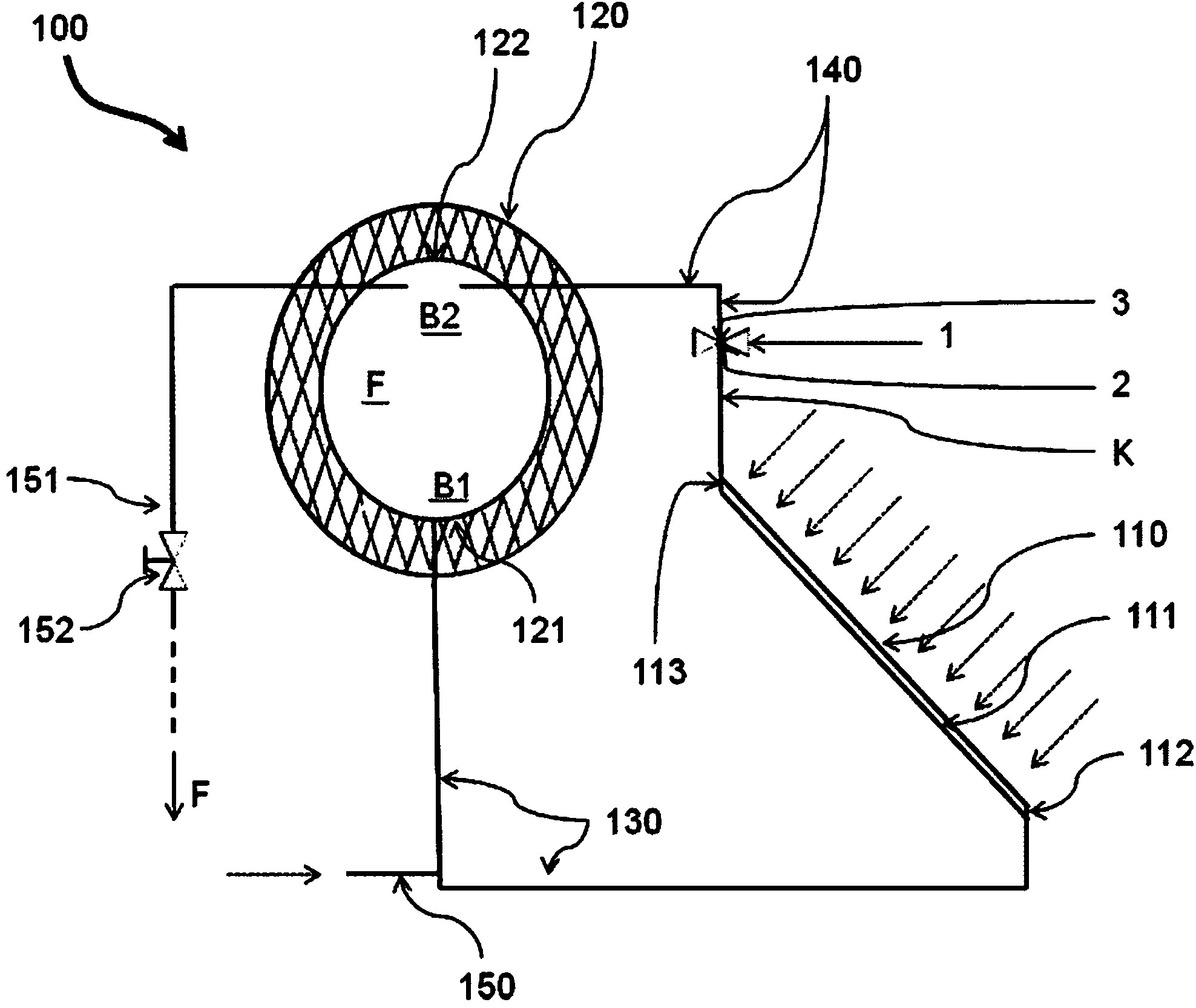
[0036] figure 1 A schematically illustrated solar energy collection device 100 is shown. The solar collector has a fluid circuit K comprising a solar collector 110 with a throughflow channel 111 having an inlet opening 112 and a plurality of outlet openings 113 which are placed measured higher than the inlet opening 112 . Furthermore, the fluid circuit K comprises a fluid reservoir 120 having a withdrawal point 121 and a feed point 122 arranged geodetically above the withdrawal point 121 . In particular, the removal point 121 is arranged in the geodetic lower region B1 of the fluid reservoir 120 . In contrast, feed-in point 122 is located in geodetic upper region B2 of fluid reservoir 120 . In this case, feed-in point 122 is arranged geodetically above outlet opening 113 of throughflow channel 111 of solar collector 110 . At the same time, fluid reservoir 120 is arranged geodetically above solar collector 110 partially, in particular approximately two-thirds.

[0037] The...


PUM


Abstract

Solar collector devices which operate according to the thermosiphon principle, in particular those made of polymer materials, can be damaged by overheating. The invention therefore relates to a valve (1) with a casing (4) which tapers in the longitudinal direction (L) from an inlet opening (2) to an outlet opening (3). A first flow area (S1) which extends beyond the inlet opening (2) in the longitudinal direction (L) is formed within the casing, and a second flow area (S2) which extends beyond the outlet opening (3) in the longitudinal direction (L) is formed outside of the casing. The first flow area (S1) and the second flow area (S2) can be fluidically connected via at least one first bypass (10) with a first bypass valve (11). The invention additionally relates to a solar collector device which operates according to the thermosiphon principle and which comprises such a valve (1).

Description

technical field [0001] The invention relates to a valve according to the preamble of claim 1 for a solar collector operating according to the thermosiphon principle, and to a solar collector according to claim 9 with such a valve. [0002] Solar energy collection devices based on the thermosiphon principle are used to obtain heat from solar energy by passive natural convection in a fluid circuit. Background technique [0003] Such solar collectors, also known as thermosyphon collectors, typically comprise a fluid reservoir arranged at least partially geodetically above the solar collector. The latter has a large extraction point arranged geometrically below and a large feed point arranged geometrically above. The solar collector has a throughflow channel with an inlet opening and an outlet opening which is arranged substantially above the inlet opening. The inlet opening of the solar collector is hydraulically connected to the withdrawal point of the fluid reservoir via a ...

Claims


Application Information

Patent Timeline
Patent Type & Authority Applications(China)
IPC IPC(8): F16K15/14F24J2/44F24J2/40
CPCY02E10/40F16K31/002F24J2/44F24J2/345F24J2/402F24S50/40F24S60/30F24S90/10
Inventor U·克莱门特
Owner ROBERT BOSCH GMBH
Why Eureka
Try Eureka