
3D (Three-dimensional) microfilament electrode array fixing device and 3D microfilament electrode array cutting method

A technology of a microwire electrode and a fixing device, applied in the field of medical devices, can solve the problems of poor consistency of the microwire electrode, difficulty in cutting the microwire electrode, and inability to accurately locate the length and angle of the microwire electrode, and achieve the effect of solving the poor consistency

Active Publication Date: 2015-03-11
SHENZHEN INST OF ADVANCED TECH CHINESE ACAD OF SCI
View PDF9 Cites 2 Cited by
  • Summary
  • Abstract
  • Description
  • Claims
  • Application Information

AI Technical Summary

Problems solved by technology

[0003] In order to improve the spatial resolution of electrodes, microwire electrode arrays are commonly used to record electrophysiological signals. In order to meet the needs of different experiments, microwire electrodes need to be cut to obtain microwire electrode arrays of different lengths. The diameter of the electrode is usually only about 20 microns, and a microwire electrode array can have as many as 128 microwire electrodes. It is very difficult to cut the microwire electrodes. The current method is mainly manual cutting with precision scissors, which is easy to damage the microwire electrodes. Insulation layer, and there is no reference when cutting, the length and angle of the microwire electrode cannot be accurately positioned, resulting in poor consistency of the microwire electrode

Method used


Image

  • 3D (Three-dimensional) microfilament electrode array fixing device and 3D microfilament electrode array cutting method
  • 3D (Three-dimensional) microfilament electrode array fixing device and 3D microfilament electrode array cutting method
  • 3D (Three-dimensional) microfilament electrode array fixing device and 3D microfilament electrode array cutting method

Examples


Embodiment Construction

[0025] The following will clearly and completely describe the technical solutions in the embodiments of the present invention with reference to the accompanying drawings in the embodiments of the present invention. Obviously, the described embodiments are only some, not all, embodiments of the present invention. Based on the embodiments of the present invention, all other embodiments obtained by persons of ordinary skill in the art without making creative efforts belong to the protection scope of the present invention.

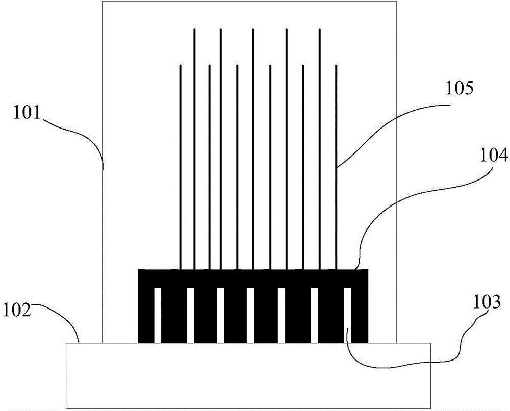
[0026] figure 1 It is a structural schematic diagram of a 3D microwire electrode array fixing device provided by an embodiment of the present invention. Such as figure 1 As shown, the 3D microwire electrode array fixing device includes a perfusion chamber 101 , a base 102 , an electrode plug 103 , a microwire electrode array socket 104 and a microwire electrode array 105 .

[0027] The lower end of the perfusion chamber 101 is in sealing connection with the ...


PUM


Abstract

The embodiment of the invention discloses a 3D (Three-dimensional) microfilament electrode array fixing device and a 3D microfilament electrode array cutting method. The 3D microfilament electrode array fixing device comprises a perfusion chamber, a base, an electrode plug, a microfilament electrode array socket and a microfilament electrode array, wherein the lower end of the perfusion chamber is in sealing connection with the base; an opening is formed in the upper end of the perfusion chamber; the base is fixedly connected with the electrode plug; the electrode plug is positioned in the perfusion chamber, and is in plugging connection with the lower surface of the microfilament electrode array socket; the microfilament electrode array is welded on the upper surface of the microfilament electrode array socket; the microfilament electrode array socket and the microfilament electrode array are positioned in the perfusion chamber. By implementing the embodiment of the invention, accurate lossless cutting of the microfilament electrode array can be realized so as to obtain the microfilament electrode array meeting different experimental requirements.

Description

technical field [0001] The invention relates to the field of medical devices, in particular to a 3D microwire electrode array fixing device and a 3D microwire electrode array cutting method. Background technique [0002] With the acceleration of the pace of life and the aging of the population structure, the incidence of neuropsychiatric diseases is increasing. In order to improve the diagnosis and treatment of neuropsychiatric diseases, the current common practice is to implant electrodes in specific brain regions of model animals and record them through electrodes. Electrophysiological signals under different stimulation conditions are used to study the relationship between the specific behavior of model animals and the discharge pattern of electrophysiological signals. In order to improve the recording quality, the spatial resolution of electrodes needs to be improved. [0003] In order to improve the spatial resolution of electrodes, microwire electrode arrays are common...

Claims


Application Information

Patent Timeline
Patent Type & Authority Applications(China)
IPC IPC(8): A61B5/0478
CPCA61B2562/125A61B5/291
Inventor 王立平鲁艺钟成
Owner SHENZHEN INST OF ADVANCED TECH CHINESE ACAD OF SCI
Learn More