Knife mechanism of hot melt adhesive bonding machine

A composite machine and hot-melt adhesive technology, applied in the direction of coating, surface coating liquid device, etc., can solve the problems of rough process, immature machine and simple cost, so as to improve the composite quality of hot-melt adhesive and reduce labor Strength and the effect of prolonging the service life

Inactive Publication Date: 2015-03-11
JIANGSU HONGYE MACHINERY
View PDF8 Cites 3 Cited by
  • Summary
  • Abstract
  • Description
  • Claims
  • Application Information

AI Technical Summary

Problems solved by technology

[0002] In general hot melt adhesive lamination machines, the gluing, glue dot transfer and surface cleaning of the patterned roller are the key points of the hot melt adhesive lamination mechanism. Glue and other phenomena, it means that the machine is immature
At present, the knife mechanism of the traditional hot melt adhesive compound machine mostly uses a square tube as the knife body, heating by an electric heating plate or an electric heating tube, the angle of the knife is not correct, and the electromagnetic iron absorbs the rubber plate. The process is relatively rough, the cost is simple, and the knife plate cannot Free to move left and right, uneven heating on the surface of the cutter body, resulting in uneven coating of hot melt adhesive, glue leakage, glue seepage and other phenomena during the working process

Method used


Image

  • Knife mechanism of hot melt adhesive bonding machine

Examples


Embodiment Construction

[0008] The specific content of the present invention will be described in detail below in conjunction with the accompanying drawings and specific embodiments.

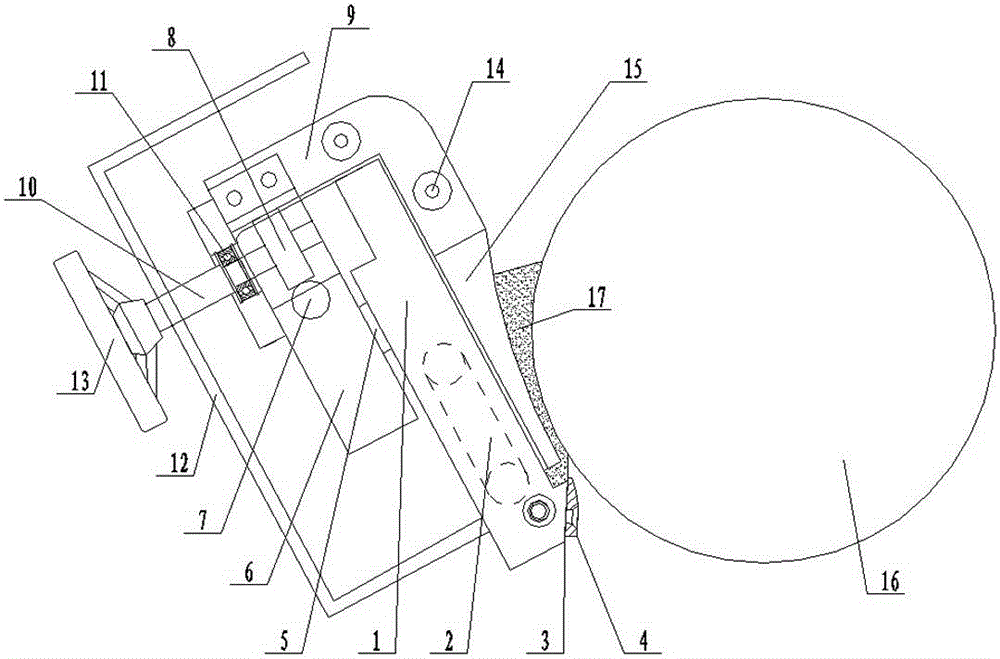
[0009] Such as figure 1 As shown, the knife mechanism of the hot melt adhesive compound machine includes: a steel plate knife body 1, a heat conduction oil heating chamber 2 is arranged in the steel plate knife body 1, and the knife blade 3 is fixedly arranged on the steel plate knife body 1 through a pressure knife plate 4 The lower end of the steel plate cutter body 1 is connected with a rack and pinion plate 6 by a pin 5, and a rack 7 and a gear 8 cooperating with the rack 7 are arranged in the rack and pinion plate 6. The upper end of the steel plate cutter body 1 and the rack and pinion plate 6 is provided with a sliding steel frame 9, the connecting rod 10 is arranged in the sliding steel frame 9 through the bearing seat 11, and one end of the connecting rod 10 extends into the rack and pinion plate 6 Connected ...


PUM


Abstract

The invention discloses a convenient-to-use knife mechanism of a hot melt adhesive bonding machine. The knife mechanism comprises a steel plate knife body, wherein a heat conducting oil heating cavity is defined in the steel plate knife body, a knife blade is fixedly arranged at the lower end of the steel plate knife body through a knife pressing plate, the upper end of the steel plate knife body is connected with a gear and rack plate through a dowel, a rack and a gear matched with the rack are arranged in the gear and rack plate, a sliding steel frame is arranged at the upper ends of both the steel plate knife body and the gear and rack plate, a connecting rod is arranged in the sliding steel frame through a bearing pedestal, one end of the connecting rod extends into the gear and rack plate and is connected with the gear, the other end of the connecting rod penetrates through a protective cover fixedly arranged on the steel plate knife body and is connected with an adhesive blocking plate moving hand wheel, and an adhesive blocking plate is arranged on the sliding steel frame on one side of the steel plate knife body through a fixing screw.

Description

technical field [0001] The invention relates to a composite device, in particular to a knife-supporting mechanism of a hot-melt adhesive composite machine. Background technique [0002] In general hot melt adhesive lamination machines, the gluing, glue dot transfer and surface cleaning of the patterned roller are the key points of the hot melt adhesive lamination mechanism. Glue and other phenomena, it means that the machine is immature. At present, the knife mechanism of the traditional hot melt adhesive compound machine mostly uses a square tube as the knife body, heating by an electric heating plate or an electric heating tube, the angle of the knife is not correct, and the electromagnetic iron absorbs the rubber plate. The process is relatively rough, the cost is simple, and the knife plate cannot Free to move left and right, the surface of the cutter body is heated unevenly, resulting in uneven coating of hot melt adhesive, glue leakage, glue seepage and other phenome...

Claims


Application Information

Patent Timeline
Patent Type & Authority Applications(China)
IPC IPC(8): B05C11/04B05C9/14
CPCB05C1/0817B05C1/003
Inventor 徐汉东还伟海卞书祥马一梓张乃扣
Owner JIANGSU HONGYE MACHINERY
Why Eureka
Try Eureka