Stripper for amorphous strip production

A technology of amorphous strips and strippers, applied in the field of iron-based amorphous spray strips, can solve problems such as easy to be moved, accumulated, unfavorable production experience, etc., to ensure verticality, improve material yield, improve production efficiency and The effect of production stability

Active Publication Date: 2015-03-11
QINGDAO YUNLU ADVANCED MATERIALS TECH CO LTD
View PDF9 Cites 7 Cited by
  • Summary
  • Abstract
  • Description
  • Claims
  • Application Information

AI Technical Summary

Problems solved by technology

Before production, first fix the height and angle of the air nozzle. During the strip production process, when the height and angle of the air nozzle need to be changed, manual changes are required. Therefore, this simple fixed stripper has the following defects: 1. 1. The structure of the stripper is relatively simple, and the air nozzle is simply fixed at a certain height, which has the disadvantage of being unstable and easy to be moved. Once the height or angle is changed, it will directly affect the output strip, making it impossible to remove from the surface of the cooling roll. Peeling, or the phenomenon that the strip splits, the strip cannot be wound, etc.
2. Even if the gas nozzle is fixed firmly, the strip cannot be successfully removed from the surface of the cooling roll due to changes in production conditions such as molten steel composition, temperature, cooling roll speed, and the state of the strip on the cooling roll surface during the production process. For conditions such as stripping, strip bifurcation, and strip not being able to be wound, it is necessary to manually adjust the height or angle of the air nozzle. However, this manual adjustment method relies heavily on the experience of the workers, and is highly random In the case of normal production after one adjustment, most of them need repeated adjustments and multiple experiments to restore normal production. This random adjustment method to respond to emergencies is not conducive to the accumulation of production experience, and it is impossible to summarize how to adjust for what situation. Gas nozzle, this problem occurs repeatedly but cannot be completely solved, seriously affecting production efficiency

Method used


Image

  • Stripper for amorphous strip production
  • Stripper for amorphous strip production

Examples


Embodiment Construction

[0023] The present invention will be described in detail below in conjunction with specific embodiments and accompanying drawings.

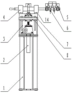
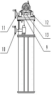
[0024] The technical solution of this embodiment is: a stripper for amorphous strip production, comprising a frame at the lower part and a main body part at the upper part, the main part includes a gas nozzle, a lifting mechanism and a rotating mechanism; the lifting mechanism It is used to adjust the height of the gas nozzle, and the rotating mechanism is used to adjust the angle of the gas nozzle.

[0025] Wherein, the main body part also includes a first axle seat, a first flat plate and an air nozzle shaft; the first flat plate is arranged on the upper part of the main body part, and the first axle seat is installed on the first flat plate; one end of the air nozzle shaft passes through the first The shaft seat, the gas nozzle is arranged at the other end of the gas nozzle shaft.

[0026] Wherein, the lifting mechanism includes a lifting wor...


PUM


Abstract

The invention belongs to the technical field of iron-base amorphous jet strips and particularly relates to a stripper for amorphous strip production. The stripper comprises a rack on the lower portion and a body portion which is disposed on the upper portion. The body portion comprises air nozzles, a lifting mechanism and a rotation mechanism. The lifting mechanism is used for adjusting the height of the air nozzles, and the rotation mechanism is used for adjusting the air nozzle angle. By means of the stripper, the air nozzles are fixed so firmly that the air nozzles cannot move easily during the production, online stripping nozzle height and angle mechanical operations can be achieved, production experience accumulation is facilitated, the problem of stripping air nozzle adjusting when production conditions are changed can be solved thoroughly, amorphous strips can be stripped from the cooling roller surface completely, and the production efficiency and the production stability are improved.

Description

technical field [0001] The invention belongs to the technical field of iron-based amorphous strip spraying, and in particular relates to a stripper for producing amorphous strips. Background technique [0002] Iron-based amorphous alloy is an alloy formed by rapid solidification to make the liquid metal atoms too late to arrange regularly. The atomic structure has the characteristics of short-range order and long-range disorder, so it has excellent electromagnetic properties. It is used in power electronics. And the field of electronic information has been widely used. Among them, iron-based amorphous materials are widely used as core materials for distribution transformers due to their high saturation magnetic induction, low loss, and high magnetic permeability, which have good economic and social benefits. [0003] At present, the amorphous strip is mainly produced by the single-roll quick quenching method, and the molten steel is poured on the high-speed rotating super ...

Claims


Application Information

Patent Timeline
Patent Type & Authority Applications(China)
IPC IPC(8): B22D11/12
CPCB22D11/0694
Inventor 李晓雨田守好姜晓鹏
Owner QINGDAO YUNLU ADVANCED MATERIALS TECH CO LTD
Why Eureka
Try Eureka