Actively unloading hydrostatic pressure spindle

A static pressure spindle and active technology, which is applied in the field of precision machine tools, can solve the problems of connection and installation surface shape accuracy changes, machine tool machining accuracy changes, axial motion errors, angular pendulum motion errors, etc., to achieve stable working conditions and motion accuracy , reduce the processing cycle and cost, and maintain the effect of processing accuracy

Active Publication Date: 2015-03-11
CHINA PRECISION ENG INST FOR AIRCRAFT IND AVIC
View PDF7 Cites 2 Cited by
  • Summary
  • Abstract
  • Description
  • Claims
  • Application Information

AI Technical Summary

Problems solved by technology

[0003] Using the current traditional rigid connection method between the machine tool spindle and the base, the machining accuracy of the machine tool spindle and the base mounting surface, especially the surface shape accuracy, will directly affect the motion accuracy of the ultra-precision hydrostatic spindle (such as radial motion error, axial motion error and angular pendulum motion error, etc.), which ultimately affects the machining accuracy of the machine tool
At the same time, if the hydrostatic spindle rigidly connected to the base is used as a workpiece axis turntable, when the weight of the workpiece to be processed changes, the spindle will directly transmit the axial load change to the machine base, resulting in a connection installation The change of surface shape accuracy, resulting in the problem that the machining accuracy of the machine tool changes with the weight of the workpiece

Method used


Image

  • Actively unloading hydrostatic pressure spindle
  • Actively unloading hydrostatic pressure spindle

Examples


Embodiment Construction

[0012] The present invention will be further described below by specific embodiment:

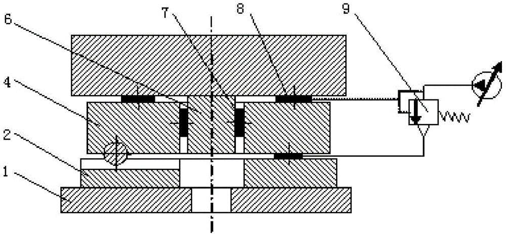
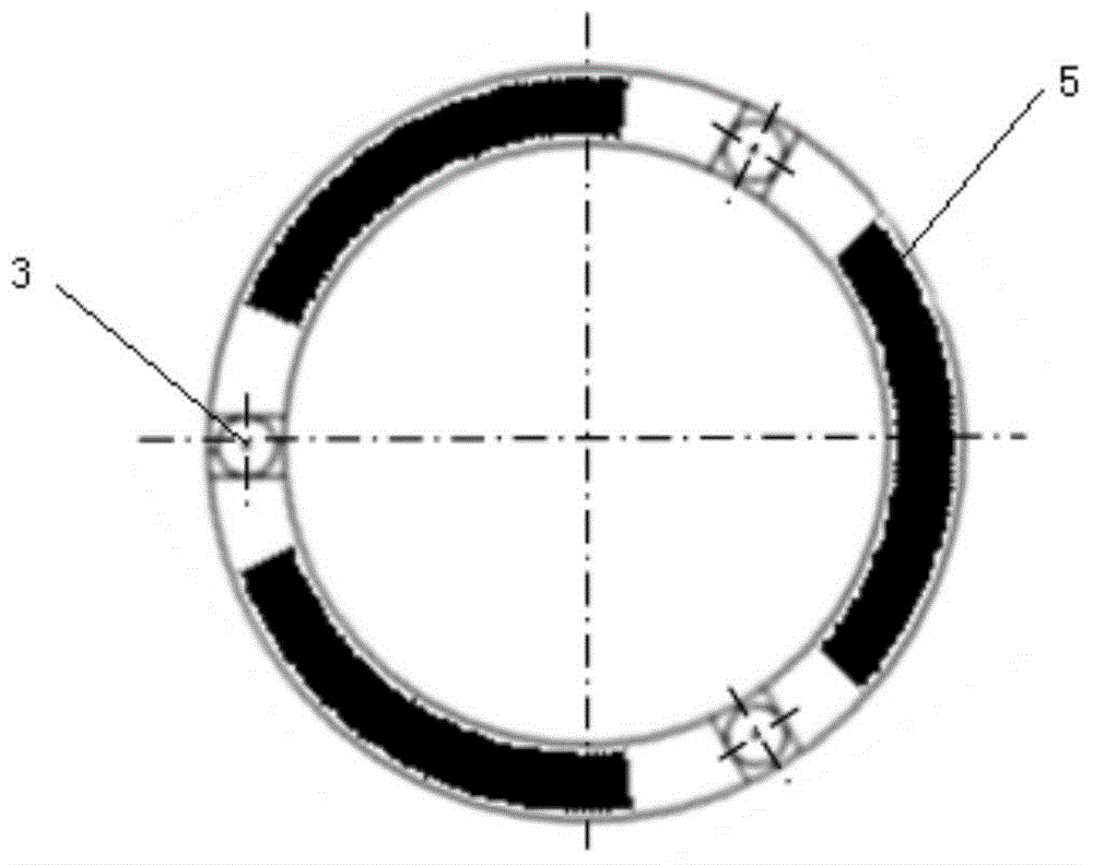
[0013] see figure 1 , in this embodiment, an active unloading hydrostatic spindle of the present invention includes a machine tool base 1, a spindle support rail 2, a support ball 3, a spindle stator 4, an unloading oil pad 5, a spindle rotor 6, and a spindle radial Oil pad 7, spindle axial oil pad 8 and unloading pressure feedback hydraulic element 9. Wherein, the main shaft support guide rail 2 with three radial V grooves is fixed on the corresponding mounting surface of the machine tool base 1 through connecting screws, and the main shaft stator 4 is supported on the main shaft support guide rail 2 by three support balls 3 through three ball sockets. The three corresponding radial V grooves are used for three-point positioning support. In addition, three unloading oil pads 5 are evenly arranged between the main shaft stator 4 and the main shaft support guide rail 2 at the positions inte...


PUM


Abstract

The invention belongs to a precision machine tool technique and specifically relates to an actively unloading hydrostatic pressure spindle. The actively unloading hydrostatic pressure spindle comprises a machine tool base, a spindle supporting guide rail, supporting balls, a spindle stator, an unloading oil pad, a spindle rotor, a spindle radial oil pad, a spindle axial oil pad and an unloading pressure feedback hydraulic element, wherein the spindle supporting guide rail with three radial V-shaped slots is fixed on the machine tool base; the spindle stator is supported in the three radial V-shaped slots of the spindle supporting guide rail through three supporting balls; the spindle rotor is statically supported on the spindle stator through the radial oil pad and the axial oil pad. According to the actively unloading hydrostatic pressure spindle provided by the invention, a three-point positioning supporting mounting mode in the form of three radial V-shaped slots-supporting balls is adopted and an active unloading technique for an unloading oil pad pressure closed ring is combined, so that the processing precision stability of the spindle and a machine tool is effectively kept and the processing period and cost of the hydrostatic pressure spindle are reduced.

Description

technical field [0001] The invention belongs to the technology of precision machine tools, and in particular relates to an active unloading hydrostatic spindle. Background technique [0002] In the manufacturing process of ultra-precision machine tools, ultra-precision hydrostatic spindles are often used to realize the rotary motion of machine workpieces or tools, and the connection between ultra-precision hydrostatic spindles and machine tool bases is usually installed in a vertical state. sits on the machine base. The traditional installation method is that the external fixed mounting surface of the spindle is directly and rigidly connected with the corresponding mounting surface of the machine base through bolts. [0003] Using the current traditional rigid connection method between the machine tool spindle and the base, the machining accuracy of the machine tool spindle and the base mounting surface, especially the surface shape accuracy, will directly affect the motion...

Claims


Application Information

Patent Timeline
IPC IPC(8): B23B19/02
CPCB23Q1/70
Inventor 罗松保张立斌杜海涛李迪
Owner CHINA PRECISION ENG INST FOR AIRCRAFT IND AVIC
Why Eureka
Try Eureka