Lathe tool

A lathe tool and tool holder technology, applied in the field of lathe tools, can solve the problems of unusable obtuse angle parts and low utilization rate of blades, etc.

Inactive Publication Date: 2015-03-11
CHANGZHOU JIANGNAN SPOKE
View PDF0 Cites 9 Cited by
  • Summary
  • Abstract
  • Description
  • Claims
  • Application Information

AI Technical Summary

Problems solved by technology

During the processing of traditional cutting tools, the commonly used blades are diamond-shaped blades. Due to the influence of the connection mode of the cutter body and the cutter body itself, the acute-angled part of the diamond-shaped blade is used as the cutting edge during processing, and the obtuse-angled part cannot be used, and the utilization rate of the blade is low.

Method used


Image

  • Lathe tool
  • Lathe tool

Examples


Embodiment Construction

[0012] The present invention will be further described below in conjunction with the accompanying drawings and specific embodiments.

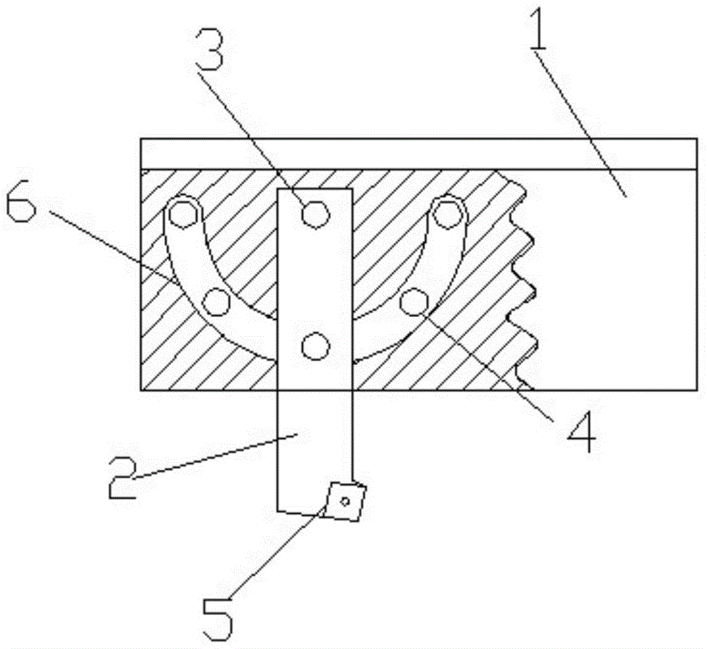
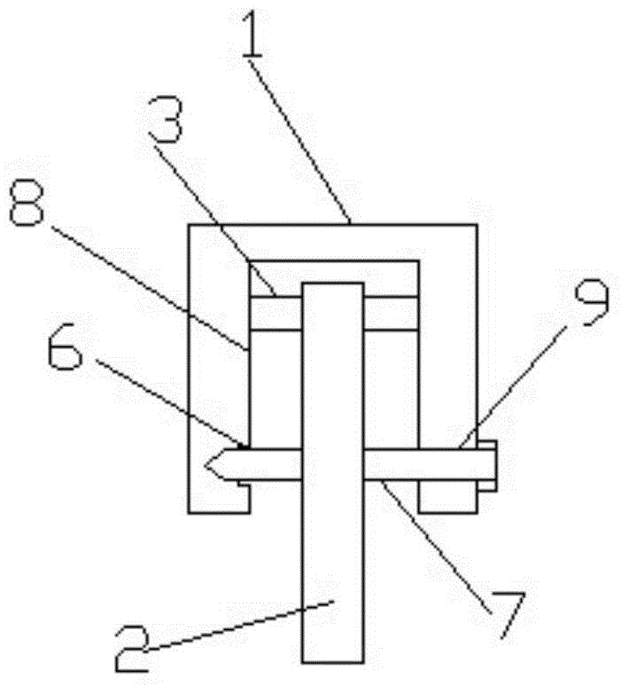
[0013] Such as figure 1 with figure 2 As shown, a lathe tool includes a tool bar 1, a tool holder 2, and a blade 5. The tool bar 1 is provided with a square groove 8, and the square groove 8 is provided with a screw 3 and a bolt 7, and the tool holder 2 is placed in the square groove 8. Inside and connected with the screw rod 3 and the bolt 7, the screw rod 3 is hinged with the knife rod 1 on both sides, and the inner wall of the knife rod 1 on one side of the square groove 8 is provided with an arc-shaped groove 6, and there are several arc-shaped grooves 6 The limit threaded hole 4 that is compatible with the bolt 7 is provided with several positioning holes 9 corresponding to the limit threaded hole 4 on the other side of the knife rod 1, and the bolt 7 passes through the positioning hole 9, the limit screw hole 4 and the knife The rods 1...


PUM


Abstract

The invention relates to a lathe tool, comprising a cutter bar, a cutter holder and a blade, wherein a square groove is formed in the cutter bar; a screw and a bolt are arranged in the square groove; the cutter holder is arranged in the square groove and is connected with the screw and the bolt; the screw is movably hinged to the cutter bar of two sides of the square groove; an arc groove is formed in the inner wall of the cutter bar on one side of the square groove; a plurality of limiting threaded holes matched with the bolt are formed in the arc groove; a plurality of positioning holes corresponding to the limiting threaded holes are formed in the cutter bar on the other side of the square groove; the bolt is connected with the cutter bar through the positioning holes and the limiting threaded holes; the blade is fixedly connected to an end angle of the cutter holder. The lathe tool has the characteristics of being simple in structure, capable of adjusting the angle and the like.

Description

technical field [0001] The invention relates to the technical field of mechanical tools, in particular to a lathe tool. Background technique [0002] A cutting tool is a tool used for cutting in mechanical manufacturing, also known as a cutting tool. In lathe processing, various tools are often used to process the inner circle, outer circle and annular groove of the workpiece. Such tools used for lathes are usually referred to as turning tools. Existing lathe tools need to be replaced regularly due to greater wear and tear during use. In this way, it is necessary to re-check the position of the tool, which wastes time and greatly reduces production efficiency. In practical applications, some mass-produced and uncomplicated workpieces are processed. During the processing of traditional cutting tools, the commonly used blades are diamond-shaped blades. Affected by the connection mode of the cutter body and the cutter body itself, the acute-angled part of the diamond-shaped b...

Claims


Application Information

Patent Timeline
Patent Type & Authority Applications(China)
IPC IPC(8): B23B27/00B23B21/00
CPCB23B27/00B23B29/04
Inventor 陈英娟
Owner CHANGZHOU JIANGNAN SPOKE
Why Eureka
Try Eureka