Aircraft skin mirror milling method and aircraft skin mirror milling device

A technology of mirror milling and aircraft skinning, which is applied in the field of mechanical processing, can solve problems such as difficulty in guaranteeing precision, milling processing, and poor rigidity, and achieve the effect of avoiding processing accidents

Active Publication Date: 2015-03-11
NANJING UNIV OF AERONAUTICS & ASTRONAUTICS
View PDF4 Cites 47 Cited by
  • Summary
  • Abstract
  • Description
  • Claims
  • Application Information

AI Technical Summary

Problems solved by technology

[0005] The purpose of the present invention is to solve the problem that the existing aircraft skin is difficult to mill and the precision is difficult to gu

Method used


Image

  • Aircraft skin mirror milling method and aircraft skin mirror milling device
  • Aircraft skin mirror milling method and aircraft skin mirror milling device
  • Aircraft skin mirror milling method and aircraft skin mirror milling device

Examples


Embodiment Construction

[0053] The present invention will be further described below in conjunction with the accompanying drawings and embodiments.

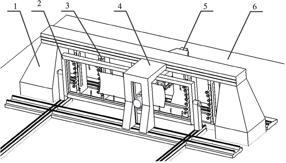
[0054] Such as figure 1 shown.

[0055] A skin mirror image milling method and equipment, mainly comprising a main body frame 1 of a machine tool, a vertical-horizontal conversion device 2, a vacuum adsorption device 3, a milling device 4, a supporting device 5, and a machine tool base 6.

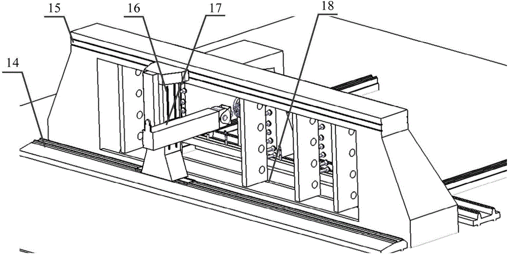
[0056] 1. Use the vertical and horizontal conversion device to clamp and position the skin.

[0057] The vertical-horizon conversion device includes the main frame, guide rails, movable beams, rotating shafts, telescopic rotating lugs and motors. In the figure, 19 is the Y-direction moving guide rail of the vertical-horizontal conversion device, 20 is the rotating shaft of the vertical-horizontal conversion device, 21 is the beam moving motor, 22 is the overall frame of the vertical-horizontal conversion, 23 is the lug clamping device, and 24 is the movable beam ,...


PUM


Abstract

An aircraft skin mirror milling method and an aircraft skin mirror milling device. The device is characterized by mainly comprising a machine tool main framework, a milling apparatus, a vertical-horizontal conversion apparatus, a lug piece holding apparatus, a flexible adsorption apparatus, a top-shore apparatus, a detection apparatus and a thickness measuring apparatus. In the device, an aircraft skin is vertically clamped by the vertical-horizontal conversion apparatus for increasing the clamping efficiency of the aircraft skin and a positioning precision of the aircraft skin is further improved with combination of a vacuum adsorption apparatus so that deformation caused by gravity can be avoided. On the basis of on-line detection by a laser displacement sensor, actual curve surface of the aircraft skin can be detected before processing and aircraft skin processing tool path can be adjusted according to an actual clamping situation for achieving self-adapting numerically-control processing. The top-shore apparatus can support the aircraft skin from backside during a milling process of the aircraft skin, thereby avoiding vibration during processing and improving stability of processing. On-line monitoring of the thickness can be achieved during the processing and thickness compensation can be provided. By means of an integrated control system, cooperative operation of units in the machine tool can be ensured and interference can be avoided.

Description

technical field [0001] The invention relates to a mechanical processing technology, in particular to a milling and clamping processing method for large thin-walled parts, in particular to a mirror image milling method and a numerical control milling device for aircraft skin parts. Background technique [0002] The skin parts are not only the exterior parts of the aircraft, but also the important force-bearing components of the aircraft. Skinned parts are generally large in size, complex in shape, and thin in thickness and poor in rigidity. The shape of the fuselage skin has a single curvature, but most of them are double curvature. The skins of the nose, tail and fairing of the fuselage are more complicated in shape. The thickness of aircraft skin parts is relatively thin (generally about 2 mm to 4 mm). According to the stress situation, some skin parts may have different thicknesses, and some skins may even have variable cross-sections. In order to reduce weight, some sk...

Claims


Application Information

Patent Timeline
IPC IPC(8): B23C3/00B23Q3/08B23Q3/06B23Q7/00B23Q17/24B23Q15/12
CPCB23C3/00B23C2215/04B23Q3/062B23Q3/088B23Q17/20B23Q17/2471
Inventor 李迎光郝小忠周鑫牟文平汤立民
Owner NANJING UNIV OF AERONAUTICS & ASTRONAUTICS
Why Eureka
Try Eureka