Control system and control method of pipeline robot
A pipeline robot and control system technology, which is applied in the field of pipeline robot control system, can solve problems such as gaps, and achieve the effects of improving pass rate, status analysis management and convenient maintenance
- Summary
- Abstract
- Description
- Claims
- Application Information
AI Technical Summary
Problems solved by technology
Method used
Image
Examples
Embodiment 1
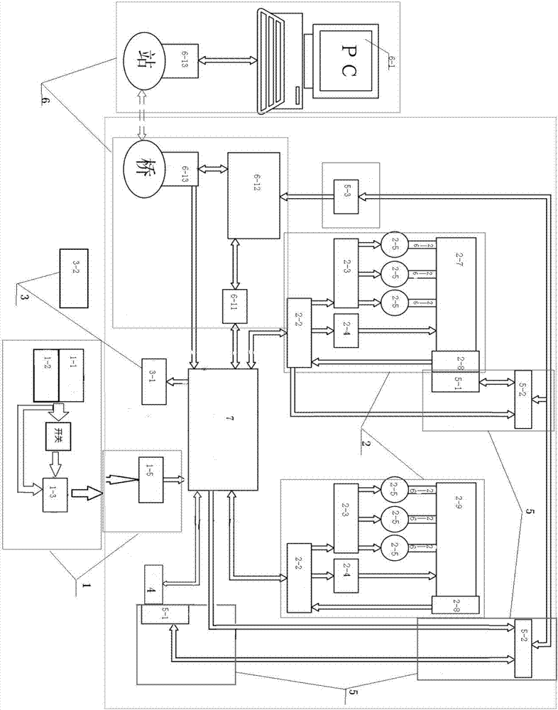
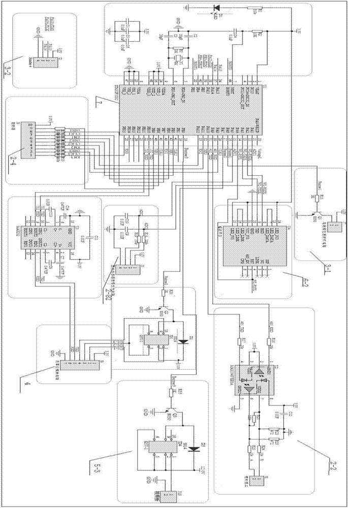
[0022] Such as figure 1 and image 3 As shown, a control system for a pipeline robot includes a power management unit 1 and an overall circuit main control unit, the overall circuit main control unit includes a main control circuit 7, a motor driver control unit 2, an electromagnetic positioning unit 3, a thickness measurement unit 4, The video unit 5 and the wireless transmission network unit 6; the power management unit 1 supplies power to the main control unit of the overall circuit, the motor driver control unit 2 controls the robot to realize various actions in the pipeline, and the electromagnetic positioning unit 3 searches for the specific position of the robot, The thickness measurement unit 4 tests the coating thickness of the pipe wall and returns the test data. The video unit 5 detects and takes pictures of the conditions inside the pipeline and conducts long-distance inspection of the interior of the pipeline. The wireless transmission network unit 6 transmits the...
Embodiment 2
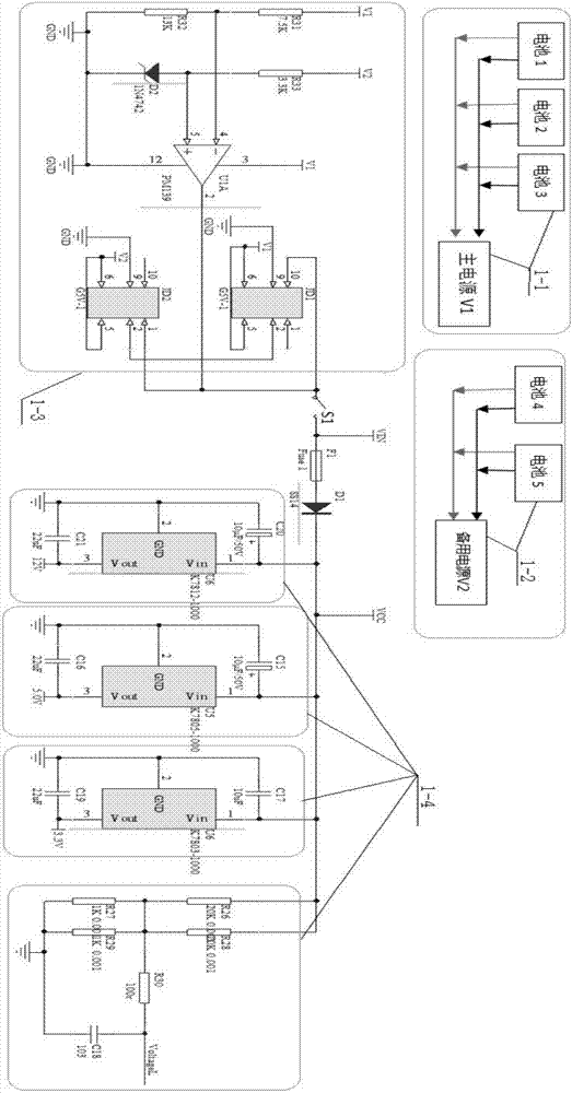
[0024] Such as figure 1 and figure 2 As shown, on the basis of Embodiment 1, the power management unit 1 includes a main circuit power supply unit 1-1, a backup battery unit 1-2, a backup battery switching circuit 1-3, a switch (S1), a variety of DC The voltage value circuit 1-4 and the voltage monitoring unit 1-5, the output terminal of the main circuit power supply unit 1-1 and the output terminal of the backup battery unit 1-2 are respectively connected to the input terminals of the backup battery switching circuit 1-3, and the backup battery switching circuit 1 The output terminal of -3 is sequentially connected in series with the switch (S1), various DC voltage value circuits 1-4, the voltage monitoring unit 1-5 and the input terminal of the main control circuit 1, the main circuit power supply unit 1-1 and the standby The battery units 1-2 are multiple sets of batteries connected in parallel; when the switch S1 is closed, the main circuit power supply unit 1-1 supplies...
PUM
 Abstract
Description
Claims
Application Information
 - R&D
- Intellectual Property
- Life Sciences
- Materials
- Tech Scout
- Unparalleled Data Quality
- Higher Quality Content
- 60% Fewer Hallucinations
Browse by: Latest US Patents, China's latest patents, Technical Efficacy Thesaurus, Application Domain, Technology Topic, Popular Technical Reports.
© 2025 PatSnap. All rights reserved.Legal|Privacy policy|Modern Slavery Act Transparency Statement|Sitemap|About US| Contact US: help@patsnap.com


