Steel stand column beam

A technology for steel columns and beams, applied in the field of steel columns, columns and beams, can solve the problems of insufficient use of sluggish residual materials in the workshop, insufficient strength of tension, pressure, and supporting force, and difficulty in ensuring welding quality, and achieves a reduction in The effect of production and operation cost, fast installation speed and strong force

Inactive Publication Date: 2015-03-11
湖北源盛钢构有限公司
View PDF6 Cites 5 Cited by
  • Summary
  • Abstract
  • Description
  • Claims
  • Application Information

AI Technical Summary

Problems solved by technology

[0003] The purpose of the present invention is to provide a steel column-column-beam, to overcome the existence of blanking in the existing steel structure column-column-beam connection node component connection mode, high precision requirements for bolt hole positions, and difficult to ensure welding quality , the strength of tension, pressure, and supporting force is not enough, there are potential safety hazards, and the sluggish surplus materials in the workshop cannot be fully utilized and other series of problems

Method used


Image

  • Steel stand column beam
  • Steel stand column beam
  • Steel stand column beam

Examples


Embodiment Construction

[0027] The present invention will be further described in detail below in conjunction with the accompanying drawings and specific embodiments.

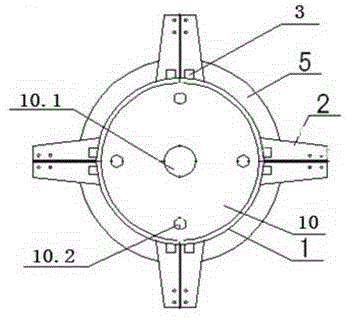
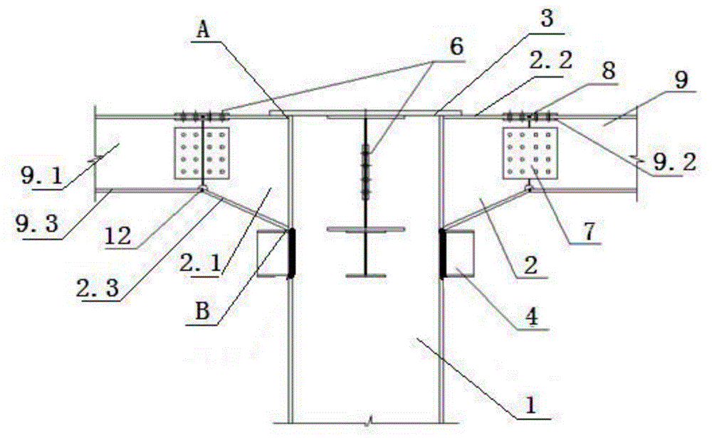
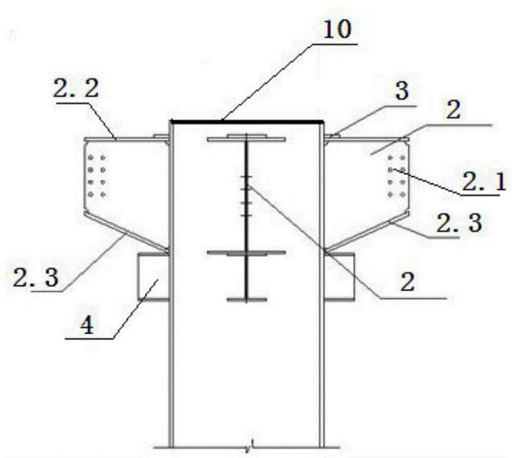
[0028] The steel column-beam as shown in the figure includes a steel column 1 and a plurality of column-beam connection node components 2 connected to the steel column 1 column wall, and a plurality of column-beam connection node components 2 are centrally symmetrical and uniform along the outer wall of the steel column 1 arrangement;

[0029] The column-beam connection node component 2 includes a web 2.1, an upper flange plate 2.2 and a lower flange plate 2.3 respectively connected to the web 2.1; the upper end surface of the upper flange plate 2.2 and the upper connection node A of the steel column 1 The limit plate 3 is fixed, the lower end surface of the lower flange plate 2.3 and the lower connection node B of the steel column 1 are provided with a limit bracket 4, and the upper flange plate 2.2 and the lower flange plate 2.3 are...


PUM


Abstract

The invention discloses a steel stand column beam. The steel stand column beam comprises a steel stand column and a plurality of column beam connecting node components, wherein the plurality of column beam connecting node components are in central symmetry and are uniformly distributed along the outer wall of the steel stand column; each column beam connecting node component comprises a web, an upper flange plate and a lower flange plate; an upper connecting node A is provided with a fixed limiting plate, and a lower connecting node B is provided with a limiting bracket; and the steel stand column beam also comprises a plurality of first clamping plates and a plurality of second clamping plates, and each clamping plate is provided with a high-strength bolt connection pair; the web is connected with a main plate of an H-shaped steel beam through the first clamping plates; the upper flange plate is connected with an upper plate of the H-shaped steel beam through the second clamping plates; a cover plate is arranged on the top end surface of the steel stand column, and a grouting hole and a plurality of vent holes are formed on the cover plate; two flange ring stiffened plates are arranged on the middle part in the steel stand column. By adopting the steel stand column beam, the steel stand column beam technology is more advanced, the process is more complete, safe and applicable, the quality is better guaranteed, the utilization rate of the plate is increased, the energy conservation and consumption reduction can be realized, the environment-friendly requirement can be met, and the component quality and construction quality can be improved.

Description

technical field [0001] The invention relates to the field of building steel structures for high-voltage power transmission, in particular to a steel column and beam. Background technique [0002] At present, the known steel structure, as a main building structure and power steel column structure, has the advantages of being reusable, free of construction waste, green and energy-saving, and material-saving. , Good anti-seismic performance, in line with the sustainable development requirements of my country and the world. In steel structure buildings, beam-column joint connection is the key to steel structure construction. At present, the beam-column joint connection methods of steel structure mainly include welding connection, bolt connection and bolt-welding connection. For the connection of "I"-shaped steel beams and columns, the common method is to directly weld the upper flange plate, web plate and lower flange plate of the "I"-shaped beam and then directly weld with the ...

Claims


Application Information

Patent Timeline
Patent Type & Authority Applications(China)
IPC IPC(8): E04B1/58
Inventor 严文凯吕金炭吕德林
Owner 湖北源盛钢构有限公司
Why Eureka
Try Eureka