Heat insulation structure and heat insulation method of polyethylene gas pipeline

A gas pipeline, heat preservation and heat insulation technology, applied in the direction of pipeline protection, heat preservation, pipeline protection through heat insulation, etc., can solve the problems of small space, difficult to ensure the horizontal clear distance, damage to the integrity of the pipeline system, etc., to achieve convenient splicing and disassembly , Conducive to the effect of maintenance

Inactive Publication Date: 2015-03-11
BEIJING GAS GRP +1
View PDF6 Cites 1 Cited by
  • Summary
  • Abstract
  • Description
  • Claims
  • Application Information

AI Technical Summary

Problems solved by technology

[0003] However, in actual engineering, due to the large number of various pipelines in the community, the space for laying pipelines is small. Therefore, when arranging polyethylene gas pipelines, it is difficult to ensure the horizontal clear distance between polyethylene gas pipelines and heat pipelines laid in parallel; At the same time, since the covering soil of thermal pipelines is generally 1.0 meters, the covering soil thickness of polyethylene gas pipelines shall not be less than 0.9 meters under the roadway, and shall not be less than 0.6 meters under non-vehicle roads (including sidewalks).
Therefore, in order to meet the above-mentioned requirements for spacing and covering soil, designers often convert steel-plastic conversion joints for polyethylene pipes into steel pipes. The advantages of excellent anti-corrosion performance and long service life of polyethylene pipes cannot be effectively utilized; Where the distance is not satisfactory, steel pipes are used, and polyethylene pipes are used for other places, and the integrity of the piping system will be destroyed.

Method used


Image

  • Heat insulation structure and heat insulation method of polyethylene gas pipeline
  • Heat insulation structure and heat insulation method of polyethylene gas pipeline
  • Heat insulation structure and heat insulation method of polyethylene gas pipeline

Examples


Embodiment Construction

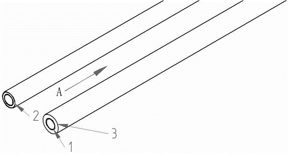
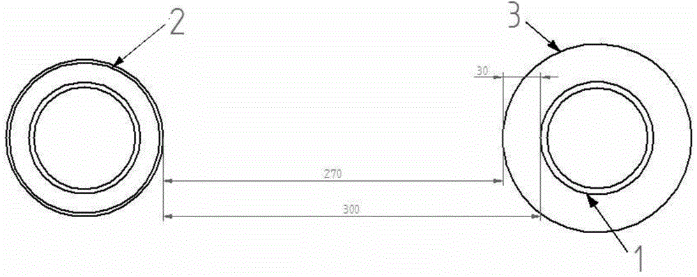
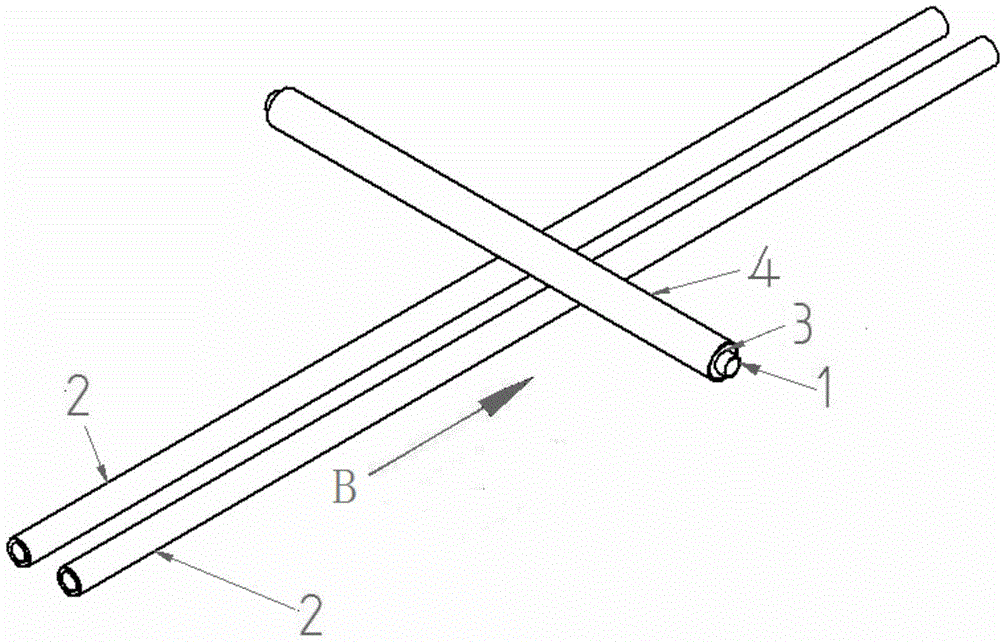
[0044] refer to Figure 1a , Figure 1b , Figure 2a and Figure 2b As shown, the main innovation of the thermal insulation structure and method of the polyethylene gas pipeline of the present invention is that when the polyethylene gas pipeline for transporting gas medium is arranged in an actual project, the polyethylene gas pipeline 1 crosses or parallels with the existing thermal pipeline 2 If the laying cannot meet the minimum horizontal or vertical clearance between the underground polyethylene gas pipeline and the thermal pipeline stipulated in CJJ 63-2008 "Technical Regulations for Polyethylene Gas Pipeline Engineering", the polyethylene gas pipeline 1 body Go up and set insulation tube shell 3 (generally adopt rigid polyurethane foam to make).

[0045] The polyurethane rigid foam insulation shell 3 is preferably a polyurethane rigid foam with a closed-cell structure and a thermal conductivity (at 50°C) of less than or equal to 0.033W / (m·K), which can play a role in ...


PUM

PropertyMeasurementUnit
Thicknessaaaaaaaaaa
Thermal conductivityaaaaaaaaaa

Abstract

The invention discloses a heat insulation structure and a heat insulation method of a polyethylene gas pipeline. The heat insulation structure comprises a group of heat pipelines embedded in soil and the polyethylene gas pipeline which is paved to be parallel to or vertical to the heat pipelines and is used for conveying a gas medium; a heat insulation pipe shell coats on the polyethylene gas pipeline; the heat insulation pipe shell at least coats a half side, facing to the heat pipelines, of the polyethylene gas pipeline. The heat insulation pipe shell is formed by mutually jointing more than two sections of unit heat insulation pipe shells in a length direction; the heat insulation pipe shell enables the gas pipeline to safely run under a surrounding temperature not more than 40 DEG C or under a lower temperature.

Description

technical field [0001] The invention belongs to the technical field of gas pipeline engineering, and in particular relates to a thermal insulation structure and a thermal insulation method for laying polyethylene gas pipelines. Background technique [0002] The industry standard of the People's Republic of China CJJ 63-2008 "Technical Regulations for Polyethylene Gas Pipeline Engineering" stipulates that when laying out underground polyethylene gas pipelines, the horizontal and vertical clearances between the underground polyethylene gas pipelines and the thermal pipelines should not be less than Specific value, and should ensure that the soil temperature around the gas pipeline is not greater than 40°C. [0003] However, in actual engineering, due to the large number of various pipelines in the community, the space for laying pipelines is small. Therefore, when arranging polyethylene gas pipelines, it is difficult to ensure the horizontal clear distance between polyethylene...

Claims


Application Information

Patent Timeline
IPC IPC(8): F16L59/10F16L59/14
CPCF16L59/10F16L59/14
Inventor 李清高顺利白丽萍冯文亮
Owner BEIJING GAS GRP
Why Eureka
Try Eureka