Working gas shunting system

A technology of shunt system and working gas, applied in pipeline system, gas/liquid distribution and storage, mechanical equipment, etc., can solve the problem of uneven gas flow, affecting the normal operation of pneumatic equipment, etc., to achieve reasonable structure and reduce heat loss. Effect

Inactive Publication Date: 2015-03-11
HEFEI DAAN PRINTING
View PDF6 Cites 5 Cited by
  • Summary
  • Abstract
  • Description
  • Claims
  • Application Information

AI Technical Summary

Problems solved by technology

[0002] In the field of printing, the working gas of some pneumatic equipment is provided by the gas source. In the prior art, the main gas supply pipeline is connected to the gas outlet of the gas source, and the branch gas supply pipeline leading to each pneumatic equipment is connected to the main gas supply pipeline. Due to the shunt effect, the gas flow distributed to each pneumatic equipment will be uneven, which will affect the normal operation of these pneumatic equipment

Method used


Image

  • Working gas shunting system

Examples


Embodiment Construction

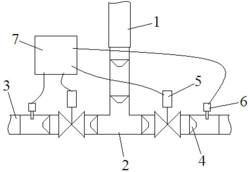
[0010] See figure 1 , A working gas distribution system, including a main gas supply pipe 1 and a three-way pipe 2. The front end of the main gas supply pipe 1 is connected to the inlet end of the three-way pipe 2, and the two outlet ends of the three-way pipe 2 are respectively A branch air supply pipe 3 is connected. The inlet end and the two outlet ends of the three-way pipe 2 are respectively provided with a plurality of tapered sleeves 4, one end of the plurality of tapered sleeves 4 facing away from the airflow direction is a large mouth end, and the other end For the small end, the two outlet ends of the three-way pipe 2 are equipped with solenoid valves 5 respectively, and the two outlet ends of the three-way pipe 2 are equipped with gas flow sensors 6 in front of the solenoid valves. The gas flow sensors 6 pass The controller 7 is respectively electrically connected to the solenoid valves on the same side.

[0011] In the present invention, the inner diameter of the lar...


PUM


Abstract

The invention discloses a working gas shunting system. The working gas shunting system comprises a main gas supply pipeline and a three-way pipe, wherein the front end of the main gas supply pipeline is connected with the gas inlet end of the three-way pipe; the two gas outlet ends of the three-way pipe are connected with a branch gas supply pipeline; a plurality of conical sleeves are arranged in the gas inlet end and the two gas outlet ends of the three-way pipe; the ends, which are back on to an air flow direction, of the conical sleeves are large-mouth ends, and the other ends are small-mouth ends; electromagnetic valves are arranged in the two gas outlet ends of the three-way pipe respectively; gas flow sensors are arranged in front of the electromagnetic valves in the two gas outlet ends of the three-way pipe respectively; the gas flow sensors are electrically connected with the electromagnetic valve on the same sides through controllers respectively. The working gas shunting system is reasonable in structure; shunting is performed through the three-way pipe, so that normal work of pneumatic equipment can be ensured; the conical sleeves in the three-way pipe can gather flowing gas rapidly, and heat loss caused by contact of certain special gas with a pipe wall can be reduced.

Description

Technical field [0001] The invention relates to the field of printing equipment, in particular to a working gas diversion system. Background technique [0002] In the printing field, the working gas of some pneumatic equipment is provided by the gas source. In the prior art, the gas outlet of the gas source is connected to the main gas supply pipeline, and the main gas supply pipeline is connected to the branch gas supply pipelines leading to the pneumatic equipment. As a result of the shunting effect, the gas flow distributed to each pneumatic equipment will be uneven, which will affect the normal operation of these pneumatic equipment. Summary of the invention [0003] The purpose of the present invention is to provide a working gas distribution system, which divides the flow through a three-way pipe, and monitors the gas flow of each branch gas supply pipeline in real time through a gas flow sensor, and then adjusts the solenoid valve through the controller without changing...

Claims


Application Information

Patent Timeline
Patent Type & Authority Applications(China)
IPC IPC(8): F17D1/04F17D3/01
Inventor 姚侃
Owner HEFEI DAAN PRINTING
Why Eureka
Try Eureka