
A 10kv cable distributed optical fiber temperature measurement method

A distributed optical fiber and cable technology, applied in thermometers, measuring devices, measuring heat and other directions, can solve the problems of endangering the safe operation of cables, difficulty in accurately determining the current carrying capacity of 10kV cables in multi-circuit intensive laying, and cable waste.

Active Publication Date: 2017-11-10
BAIYUN POWER SUPPLY BUREAU GUANGZHOU POWER SUPPLY BUREAU
View PDF2 Cites 0 Cited by
  • Summary
  • Abstract
  • Description
  • Claims
  • Application Information

AI Technical Summary

Problems solved by technology

[0006] At present, it is difficult to accurately determine the ampacity of 10kV cable multi-circuit dense laying, and dense laying often becomes the bottleneck that limits the current carrying capacity of 10kV cables. Whether filling low thermal resistance filling materials on the sides of 10kV cables can increase their ampacity needs to be checked online. The monitoring technology grasps the operation status of the cables in the case of dense laying in real time, and prevents the cables from endangering the safe operation of the cables due to the load exceeding its allowable current-carrying capacity, or causing waste due to the long-term operation of the cables below their actual current-carrying capacity

Method used


Image

  • A 10kv cable distributed optical fiber temperature measurement method
  • A 10kv cable distributed optical fiber temperature measurement method
  • A 10kv cable distributed optical fiber temperature measurement method

Examples


Embodiment 1

[0016] The Lingbo substation is selected as the test object, which is a 10kV substation outgoing cable.

[0017] At the 10kV cable laying site, first use a pipe threader to thread the pipe, lay the 10kV cable in the pipe, and then use a flushing vehicle to flush the mud in the pipe. The distributed optical fiber temperature measurement system used in this embodiment is a distributed optical fiber temperature measurement system (model: ZD-2) produced by Ningbo Zhendong Optoelectronics Co., Ltd. The distributed optical fiber temperature measurement system includes an optical fiber thermometer and a temperature sensor The optical fiber and the optical fiber thermometer are installed in the duty room of the power station, equipped with 220V power supply, and the temperature-sensing optical fiber is led out from the duty room, and the temperature-sensing optical fiber is penetrated into the tube. The pipe is guided to the exit of the second working well, then turned back, and penet...


PUM


Abstract

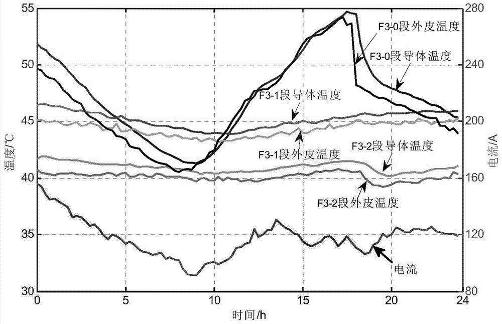
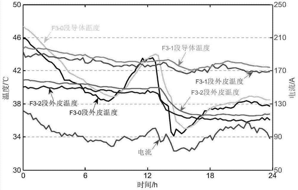
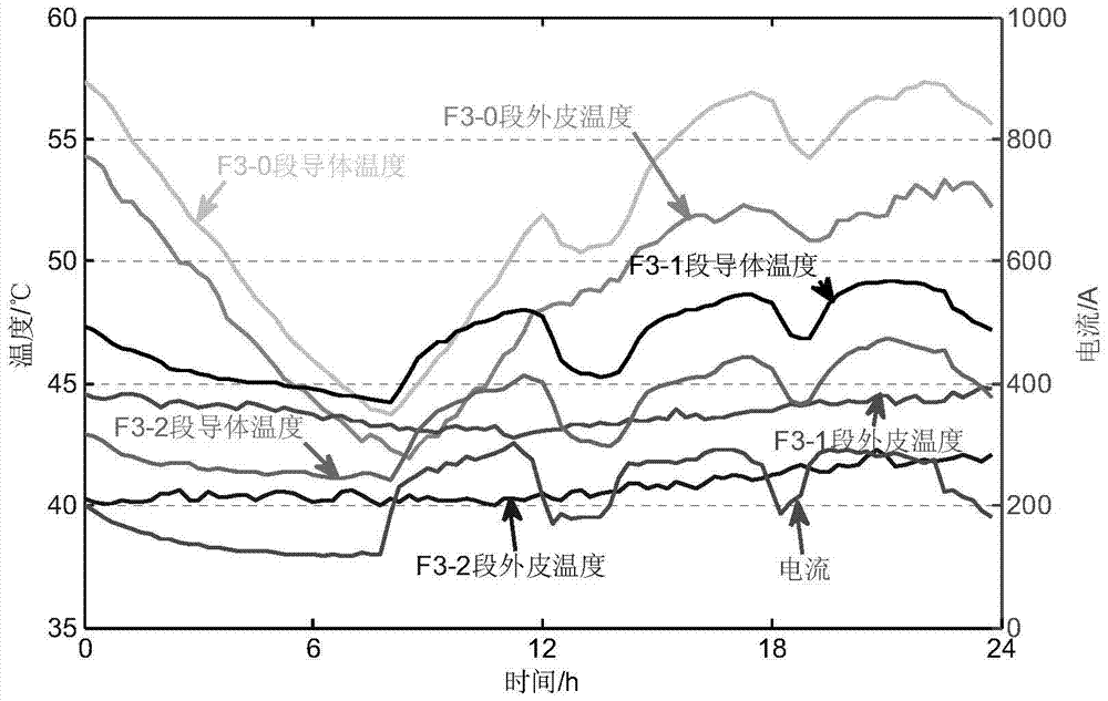
The invention discloses a 10kV cable distributed optical fiber temperature measurement method. At the 10kV cable laying site, first use the pipe threader to pass through the pipe, lay the 10kV cable in the pipe, then wash the mud in the pipe, and put the temperature-sensing optical fiber of the distributed optical fiber temperature measurement system into the pipe, and each temperature-sensing optical fiber is threaded into a In the pipe with cable, use the pipe threader to guide to the exit of the second working well, then turn back, and penetrate into another pipe with cable until it returns to the original pipe entrance. The process of threading the pipe makes the temperature-sensitive optical fiber close to the cable skin , fasten with cable ties at the exit and the position passing through the well, and attach a sign board, then fill the filling medium into the gap where the cable passes through the pipe, seal the two ends with sealing materials, and use the distributed optical fiber temperature measurement system The optical fiber temperature measurement host implements the data of receipt of temperature-sensing optical fiber, and displays the temperature trajectory of the optical cable in real time, so as to obtain the relationship between the temperature and current of the operating cable, and proposes the correction coefficient of the cable ampacity when using different filling media in different laying methods recommended value.

Description

Technical field: [0001] The invention belongs to the field of multi-circuit intensive laying of cables, and in particular relates to a method for measuring the temperature of a 10kV cable distributed optical fiber. Background technique: [0002] There have been applications in foreign countries such as the United States, the United Kingdom, and Hong Kong to improve the heat dissipation conditions of direct-buried and pipe-laying cables by backfilling low-thermal-resistance media and pumping heat-conducting media into the pipes. [0003] At present, domestic power cable laying methods mainly include direct burial, pipe arrangement, cable trench and tunnel, among which direct burial and pipe arrangement account for the vast majority. Therefore, how to increase the ampacity of the cables in the direct burial and pipe laying sections, increase the transmission capacity of the cables, and maximize the benefits of the cables has great practical significance. [0004] In order to ...

Claims


Application Information

Patent Timeline
Patent Type & Authority Patents(China)
IPC IPC(8): G01K11/32
Inventor 周凡珂王晓兵许继葵钱华胡日鹏周庆辉索智鑫廖伟焱陈剑倪建明苏瑞波林育明张崇超
Owner BAIYUN POWER SUPPLY BUREAU GUANGZHOU POWER SUPPLY BUREAU
Learn More