
A remote monitoring system for medical equipment

A remote monitoring system and medical equipment technology, applied in the direction of electrical program control, sequence/logic controller program control, etc., can solve the problems of damaged medical equipment, medical equipment operation adjustment, monitoring and control can not be realized at the same time, to achieve Ensure the effect of normal operation

Active Publication Date: 2018-11-02
GUANGDONG POLYTECHNIC NORMAL UNIV
View PDF3 Cites 0 Cited by
  • Summary
  • Abstract
  • Description
  • Claims
  • Application Information

AI Technical Summary

Problems solved by technology

[0003] Monitoring and control cannot be realized at the same time, only a single remote monitoring or remote control can be realized
It causes the simplification of its functions. When the monitored data is different from the preset value, the operation of the medical equipment cannot be adjusted in time, and it is easy to cause safety accidents and damage the medical equipment.
When performing remote control on medical equipment, the operator cannot grasp the operation status of the medical equipment in real time and whether the operation of the medical equipment is normal. Only relying on the operator's experience to control the medical equipment can easily lead to errors in judgment. Improper operation, damage to medical equipment
Therefore, a single remote monitoring or control is an incomplete system, and it is necessary to realize monitoring and control at the same time to ensure the normal operation of medical equipment

Method used


Image

  • A remote monitoring system for medical equipment
  • A remote monitoring system for medical equipment

Examples


Embodiment Construction

[0020] The present invention will be further described below in conjunction with accompanying drawing and specific embodiment:

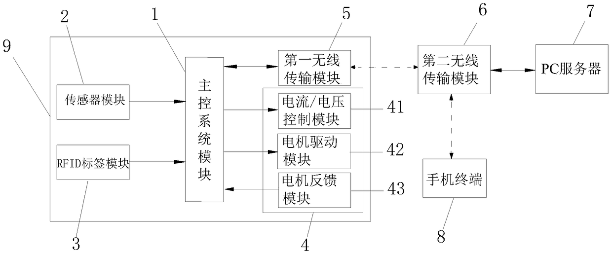
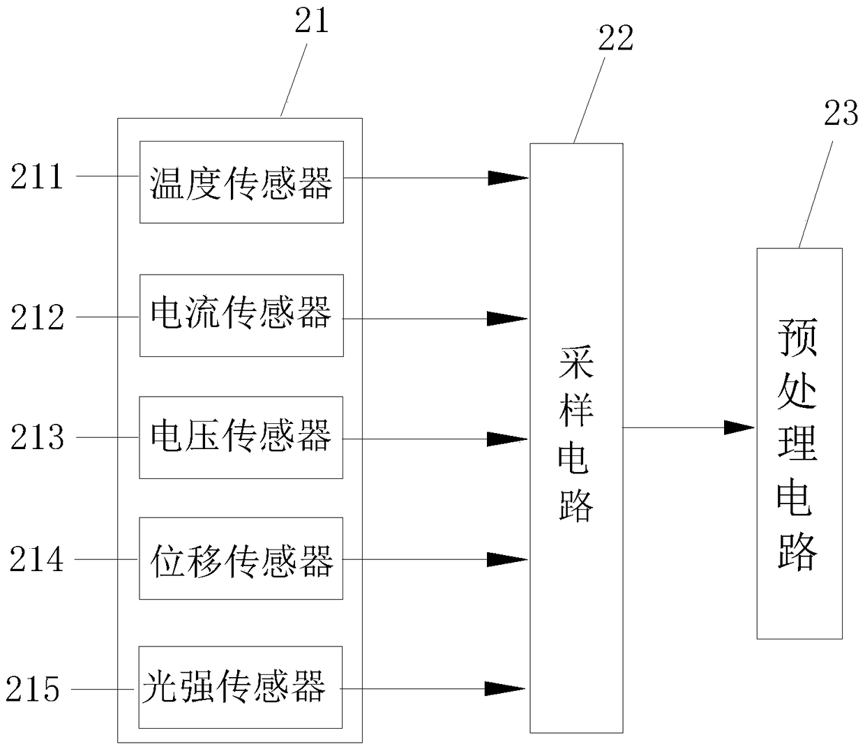
[0021] Such as Figure 1~2 As shown, the medical equipment remote monitoring system of the present invention mainly includes a main control system module 1, a sensor module 2, an RFID tag module 3, a motion control module 4, a first wireless transmission module 5, a second wireless transmission module 6, Server 7 and mobile phone terminal 8. Specifically, the main control system module 1 , the sensor module 2 , the RFID tag module 3 , the motion control module 4 and the first wireless transmission module 5 are all set on one medical device 9 . Among them, the sensor module 2 is responsible for collecting relevant information of the medical equipment 9 and is connected with the main control system module 1, and transmits the collected status information of the medical equipment 9 to the main control system module 1; the RFID tag module 3 is responsib...


PUM


Abstract

The invention relates to the technical field of remote monitoring, and particularly relates to a medical equipment remote monitoring system which mainly comprises a master control system module, a sensor module, an RFID tag module, a movement control module, a first wireless transmission module, a second wireless transmission module, a server and a mobile phone terminal. The sensor module transmits the acquired medical equipment state information to the master control system module. The RFID tag module transmits the acquired medical equipment consumable information to the master control system module. The master control system module is respectively connected with the movement control module and the first wireless transmission module. The movement control module controls medical equipment. The server is connected with the second wireless transmission module which is respectively connected with the first wireless transmission module and the mobile phone terminal in a wireless communication way.

Description

technical field [0001] The invention relates to the technical field of remote monitoring, in particular to a remote monitoring system for medical equipment. Background technique [0002] The prior art solutions generally implement remote monitoring technology or remote control technology alone. Remote monitoring technology: By using a single sensor network, the data collected by the sensor is transmitted to the data collector and then transmitted to the database through wireless transmission in one direction. The mobile terminal can interact with the database, analyze and record the data, but cannot Remote control of medical equipment can only monitor the operation of medical equipment in real time. Remote control technology: Controlling medical equipment through wireless network client wireless communication can only reflect remote control, and cannot monitor the operation of medical equipment in real time. Therefore, the existing technical solution lacks the advantage of...

Claims


Application Information

Patent Timeline
Patent Type & Authority Patents(China)
IPC IPC(8): G05B19/04
CPCG05B19/04
Inventor 罗永顺蔡泳成
Owner GUANGDONG POLYTECHNIC NORMAL UNIV
Learn More