

Optical lens
An optical lens and lens technology, applied in the field of optical lens, to achieve the effects of small distortion, high light-passing performance, and aberration correction
- Summary
- Abstract
- Description
- Claims
- Application Information
AI Technical Summary
Problems solved by technology
Method used
Image

Examples
Embodiment 1
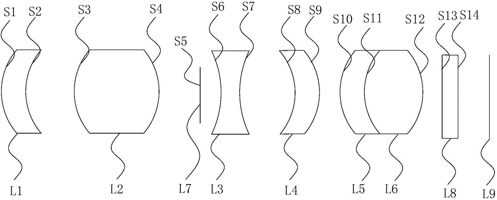
[0050] figure 1 It is a structural schematic diagram of an optical lens provided in a specific embodiment of the present invention. Such as figure 1 As shown, a kind of optical lens of the present invention, from the object side to the image side, includes: a front lens group with positive refractive power, a diaphragm element L7, a rear lens group with positive refractive power, and a color filter L8, and imaging surface L9;
[0051] Wherein, the front lens group includes in sequence from the object side to the image side: a first lens L1 and a second lens L2, and the first lens L1 is a crescent-shaped lens with a negative refractive power and a concave surface facing the image side, so The second lens L2 is a biconvex lens with positive refractive power; the rear lens group includes in sequence from the object side to the image side: the third lens L3, the fourth lens L4, the fifth lens L5 and the sixth lens L6, so The third lens L3 is a biconcave lens with negative refra...
Embodiment 2
[0087] Embodiment 2: It should be noted that the difference between this embodiment and Embodiment 1 lies in that the structure of the cemented lens in the rear lens group in this embodiment is different.
[0088] Figure 5 It is a structural schematic diagram of another optical lens provided in the specific embodiment of the present invention. Such as Figure 5 As shown, a kind of optical lens of the present invention, from the object side to the image side, includes: a front lens group with positive refractive power, a diaphragm element L7, a rear lens group with positive refractive power, and a color filter L8, and imaging surface L9;
[0089] Wherein, the front lens group includes in sequence from the object side to the image side: a first lens L1 and a second lens L2, and the first lens L1 is a crescent-shaped lens with a negative refractive power and a concave surface facing the image side, so The second lens L2 is a biconvex lens with positive refractive power; the r...
PUM
 Abstract
Description
Claims
Application Information