

Reconfiguration method of real-time distributed simulation platform
A distributed simulation and simulation platform technology, applied in the field of real-time distributed simulation platform, can solve the problems of difficult cutting of modules, unclear module boundaries, high module coupling, etc., and achieve the effect of easy operation and implementation, saving manpower and time
- Summary
- Abstract
- Description
- Claims
- Application Information
AI Technical Summary
Problems solved by technology
Method used
Image

Examples
Embodiment Construction
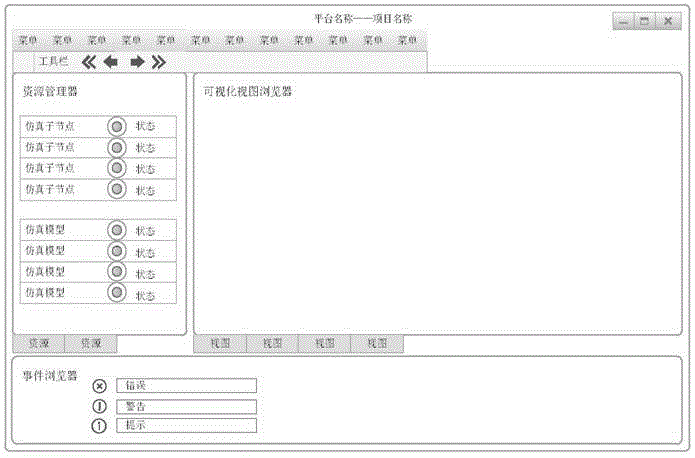
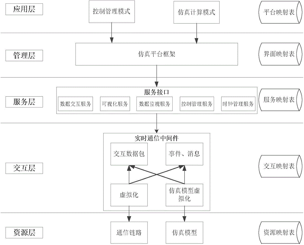
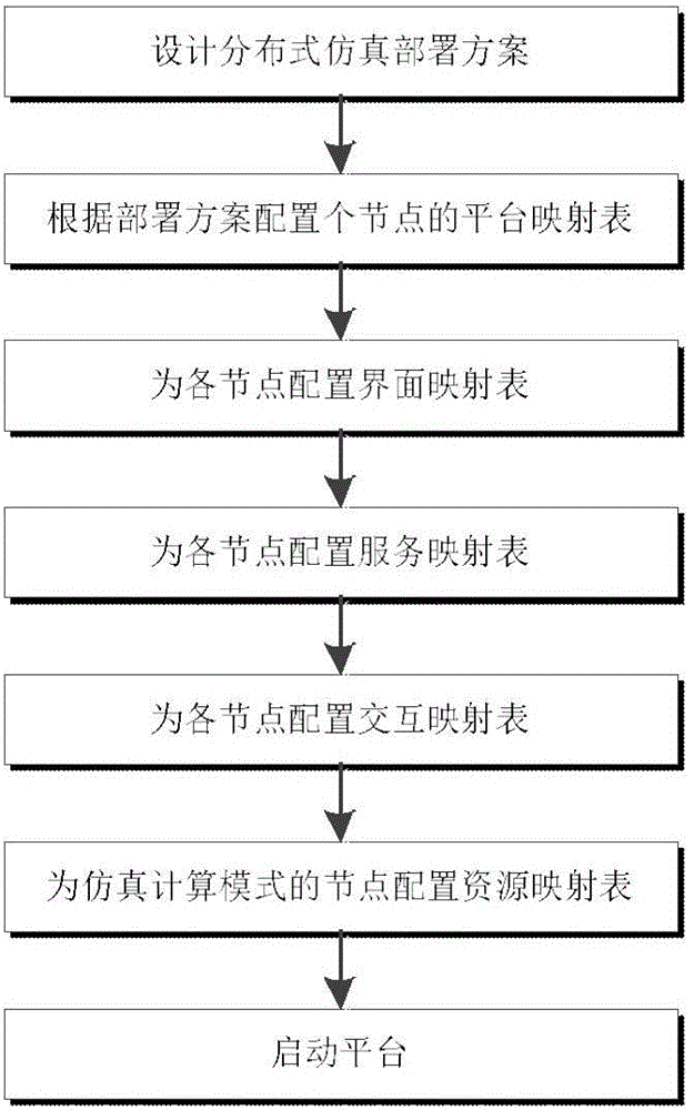
[0024] refer to figure 1 figure 2 . In creating the real-time distributed simulation platform architecture, the simulation platform framework is divided into five-layer models from top to bottom, and its hierarchical model includes application layer, management layer, service layer, interaction layer, and resource layer. All have related models and components, and correspond to a mapping table to describe the attributes, functions, parameters and other information of the hierarchical models and components. Each level is relatively independent. It only provides interfaces to the upper level and cannot be accessed, and the lower level is accessed through the interface of the lower level. The data interaction between various model resources is realized through the service interface in the service layer; then the sub-nodes are divided into two modes of control management and simulation calculation, and are included in the application layer.
[0025] a) Application layer
[00...
PUM
 Abstract
Description
Claims
Application Information