Method for correcting installation thrust of engine model

A thrust method and engine technology, applied in the aviation field, can solve the problems of the resistance loss of the rear body of the engine nozzle, the inability to meet the real-time simulation, and the complex mutual restriction relationship, so as to achieve the effect of simple software development, wide applicability, and risk reduction.

Active Publication Date: 2015-03-11
SHENYANG AIRCRAFT DESIGN INST AVIATION IND CORP OF CHINA
View PDF7 Cites 11 Cited by
  • Summary
  • Abstract
  • Description
  • Claims
  • Application Information

AI Technical Summary

Problems solved by technology

Due to the complex mutual constraints between the various components of the engine, it is necessary to iterate the values ​​of multiple parameters repeatedly when finding the common working point, and the simulation cycle is long
[0004] The existing intake loss model usually calculates the overflow resistance of the intake, the suction resistance of the boundary layer, the bypass deflation resistance and the auxiliary intake resistance, and the intake loss is obtained by iteratively solving the equations, and the simulation cycle is long
[0005] The existing power extraction loss model usually uses empirical formulas to correct the engine power extraction loss, and the simulation accuracy is low
[0006] The existing nozzle body resistance loss model usually calculates the pressure resistance caused by the boundary layer separation of the nozzle outflow, combined with the engine component level model, the engine nozzle body resistance loss is obtained by iteratively solving the equations, and the simulation cycle is also very long
[0007] The engine installation thrust simulation model established by this method has average simulation accuracy and a simulation cycle of several seconds, which cannot meet the requirements of real-time simulation.

Method used


Image

  • Method for correcting installation thrust of engine model
  • Method for correcting installation thrust of engine model
  • Method for correcting installation thrust of engine model

Examples


Embodiment

[0053] Embodiment: This example is an American F110 turbofan engine equipped with an F16 aircraft. A correction method combining testing and interpolation methods is used to correct the engine performance model used in the engine performance simulation after installation. Specific steps are as follows:

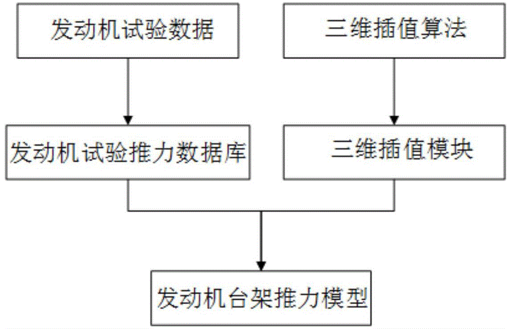
[0054] 1) Carry out the engine ground bench test and high-altitude bench test, given the aircraft flight state (flight altitude H and flight Mach number Ma) and throttle lever angle PLA, get the engine bench thrust Fi data table; design point H = 0km, Ma =0, PLA=110°, the thrust of the engine stand Fi=105.9kN measured in the test:

[0055] 2) Use the interpolation method to model, based on the engine thrust data table, use the three-dimensional interpolation algorithm to construct the engine bench thrust model Ft, see figure 1 :

[0056] Ft = f(H, Ma, PLA)

[0057] In the formula:

[0058] flight height H;

[0059] Flight Mach number Ma;

[0060] Throttle stick angle PLA...


PUM


Abstract

The invention belongs to a power device system in the technical field of aviation, and relates to a method for correcting the installation thrust of an engine model. The method comprises the following steps: (1.1) acquiring an engine bench thrust Fi data table; (1.2) constructing an engine bench thrust model Ft by adopting a three-dimensional interpolation algorithm; (1.3) carrying out an air inlet blowing test; (1.4) modeling by using an interpolation method; (1.5) establishing an air inlet loss correction model K1; (1.6) building a power extraction loss coefficient database; (1.7) establishing a power extraction loss correction model K2; (1.8) building a spray pipe afterbody resistance loss coefficient database; (1.9) establishing a spray pipe afterbody resistance loss correction model K3; (1.10) finishing modelling of an engine installation thrust model. The method has the advantages of high calculation accuracy, simulation instantaneity, easiness in implementation, short modeling period and high engineering applicability.

Description

technical field [0001] The invention belongs to the power plant system in the technical field of aviation, and relates to a thrust correction method for engine model installation. Background technique [0002] In aircraft design, engine simulation models are often used to carry out aircraft simulation verification based on performance simulation results. The engine simulation model is an engine installation thrust performance model including intake and exhaust losses after the engine is installed. [0003] The existing engine bench thrust model is modeled by the component method, which is characterized in that the characteristics of each component are known, the control scheme is selected, the common working point is determined according to the common working conditions of each component, and then the engine thrust and fuel consumption rate are calculated. Due to the complex mutual constraints among the various components of the engine, it is necessary to repeatedly iterate...

Claims


Application Information

Patent Timeline
Patent Type & Authority Applications(China)
IPC IPC(8): G06F17/50
Inventor 刁科锋吴敬伟刘素萍刘耀阳刘方兴
Owner SHENYANG AIRCRAFT DESIGN INST AVIATION IND CORP OF CHINA
Why Eureka
Try Eureka