Waveguide rotary joint

A technology of rotating joints and waveguides, applied in the field of electromagnetic wave propagation, can solve the problems of large signal power loss, limitation and reflection, poor return loss index, etc., to achieve the effect of improving impedance matching and reducing signal power loss

Inactive Publication Date: 2015-03-11
SICHUAN LONGRUI MICROELECTRONICS
View PDF5 Cites 1 Cited by
  • Summary
  • Abstract
  • Description
  • Claims
  • Application Information

AI Technical Summary

Problems solved by technology

[0003] The waveguide rotary joint can be divided into rectangular waveguide and circular waveguide according to the shape of the waveguide cross-section. Although there are many different waveguide forms, the traditional waveguide rotary joints are composed of waveguides that overlap and connect with each other, which will cause electromagnetic waves in The propagation path in the waveguide channel is long, so it is easily affected by the restriction of the inner wall of the waveguide and the impedance effect of reflection, resulting in poor impedance matching, poor return loss index, and large signal power loss.

Method used


Image

  • Waveguide rotary joint
  • Waveguide rotary joint

Examples


Embodiment Construction

[0011] The following will clearly and completely describe the technical solutions in the embodiments of the present invention with reference to the accompanying drawings in the embodiments of the present invention. Obviously, the described embodiments are only some, not all, embodiments of the present invention. Based on the embodiments of the present invention, all other embodiments obtained by persons of ordinary skill in the art without making creative efforts belong to the protection scope of the present invention.

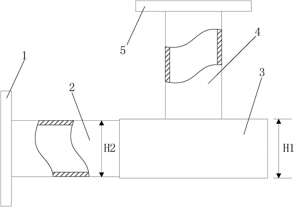
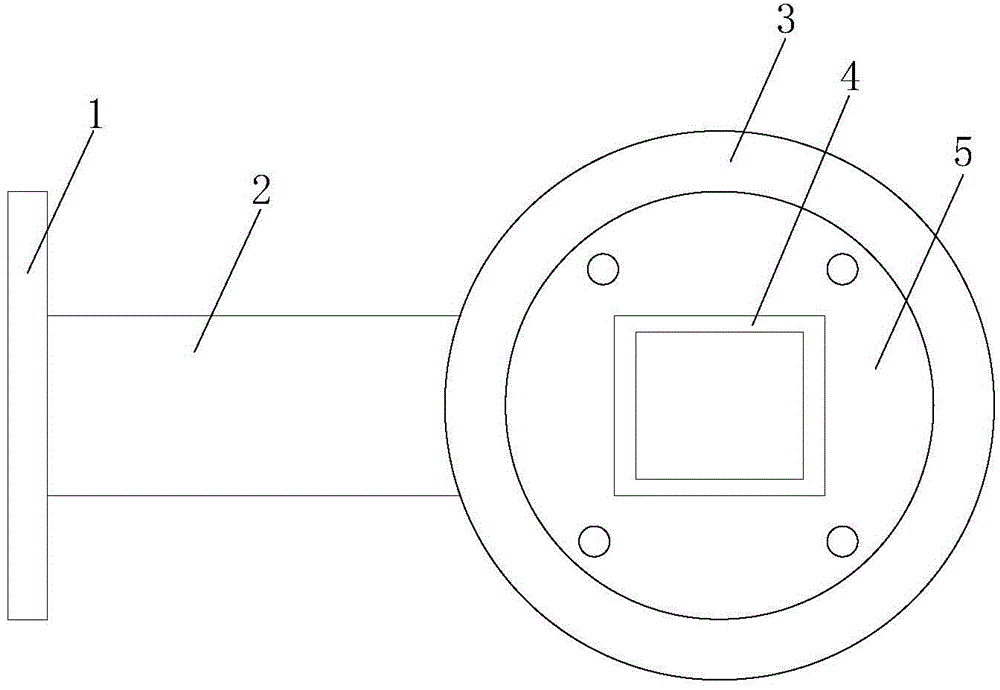
[0012] Please also see figure 1 and figure 2 . The waveguide rotary joint of the embodiment of the present invention includes a first flange 1, a first rectangular waveguide 2, a ring waveguide 3, a second rectangular waveguide 4 and a second flange 5, the first rectangular waveguide 2 and the second rectangular waveguide 4 Placed perpendicular to each other, the first flange 1 is installed at one end of the first rectangular waveguide 2, the height H1 of t...


PUM


Abstract

The invention provides a waveguide rotary joint. The waveguide rotary joint comprises a first flange, a first rectangular waveguide, an annular waveguide, a second rectangular waveguide and a second flange, wherein the first rectangular waveguide and the second rectangular waveguide are arranged perpendicular to one another, the first flange is mounted at one end of the first rectangular waveguide, the height of the annular waveguide is not smaller than the height of the first rectangular waveguide, the other end of the first rectangular waveguide is connected with the peripheral surface of the annular waveguide, the second flange is mounted at one end of the second rectangular waveguide, the other end of the second rectangular waveguide is connected with the end surface of the annular waveguide, and the second rectangular waveguide and the annular waveguide are coaxially arranged. According to the invention, the waveguide rotary joint can shorten the transmission path of electromagnetic waves in a waveguide channel.

Description

technical field [0001] The invention relates to the technical field of electromagnetic wave propagation, in particular to a waveguide rotary joint. Background technique [0002] In the microwave signal transmission system, in order to enable the antenna to search, track and measure targets at all times during work, it is often required that the azimuth angle of the antenna can be adjusted by 360 degrees, and the elevation angle can be adjusted by ±90 degrees. Therefore, a waveguide rotary joint must be installed between the network and the feed source to ensure effective transmission of microwave signals. [0003] The waveguide rotary joint can be divided into rectangular waveguide and circular waveguide according to the shape of the waveguide cross-section. Although there are many different waveguide forms, the traditional waveguide rotary joints are composed of waveguides that overlap and connect with each other, which will cause electromagnetic waves in The propagation p...

Claims


Application Information

Patent Timeline
Patent Type & Authority Applications(China)
IPC IPC(8): H01P1/06
Inventor 弋建利何激扬夏敏
Owner SICHUAN LONGRUI MICROELECTRONICS
Why Eureka
Try Eureka