Eureka AIR delivers breakthrough ideas for toughest innovation challenges, trusted by R&D personnel around the world.

A fluorescent wheel fixing structure and laser projection device

A fixed structure and fluorescent wheel technology, applied in projection devices, optics, instruments, etc., can solve the problems of large volume of light source modules and the whole machine, low fixing accuracy, and long heat transmission path, so as to shorten the heat transmission path and improve User experience, the effect of improving the cooling effect

Active Publication Date: 2021-06-01
QINGDAO HISENSE LASER DISPLAY CO LTD
View PDF0 Cites 0 Cited by
  • Summary
  • Abstract
  • Description
  • Claims
  • Application Information

AI Technical Summary

Problems solved by technology

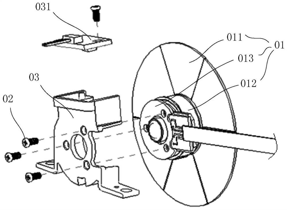
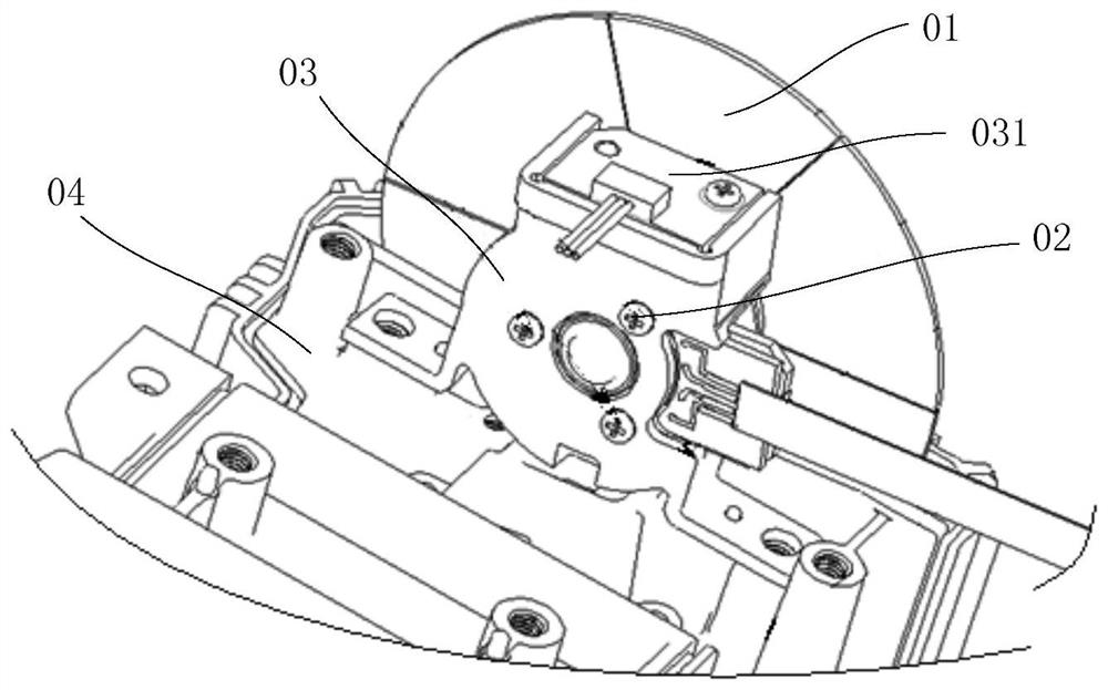
However, in the solution of the prior art, the structure of the side wall of the light source housing 04 and the adapter bracket 03 will hinder the airflow generated by the rotation of the fluorescent wheel 01, which is not conducive to the heat dissipation of the fluorescent wheel 01 through the airflow of its own rotation. Moreover, the motor 012 generates The heat needs to be transferred to the adapter bracket 03 through the heat dissipation aluminum plate 013, and then transferred to the light source housing 04 by the adapter bracket 03 to dissipate heat. The heat propagation path is long and the heat dissipation effect is not good.
Therefore, the fluorescent wheel 01 needs to be set to a relatively large size (generally more than 65 mm in diameter) to meet the heat dissipation requirements, thereby making the light source module and the whole machine bulky and costly
In addition, since the fluorescent wheel 01 of the prior art is fixed to the light source housing 04 through the adapter bracket 03, during the rotation of the fluorescent wheel 01, on the one hand, the fixing accuracy of the adapter bracket 03 and the light source housing 04 is low, and the adapter bracket 03 will vibrate, which will generate noise; on the other hand, the structure of the adapter bracket 03 will hinder the airflow generated by the rotation of the fluorescent wheel 01, and will also generate noise, which will affect the user experience

Method used


Image

  • A fluorescent wheel fixing structure and laser projection device
  • A fluorescent wheel fixing structure and laser projection device
  • A fluorescent wheel fixing structure and laser projection device

Examples


Embodiment Construction

[0031] The following will clearly and completely describe the technical solutions in the embodiments of the present invention with reference to the accompanying drawings in the embodiments of the present invention. Obviously, the described embodiments are only some of the embodiments of the present invention, not all of them. Based on the embodiments of the present invention, all other embodiments obtained by persons of ordinary skill in the art without making creative efforts belong to the protection scope of the present invention.

[0032] In describing the present invention, it is to be understood that the terms "center", "upper", "lower", "front", "rear", "left", "right", "vertical", "horizontal", The orientations or positional relationships indicated by "top", "bottom", "inner", "outer", etc. are based on the orientations or positional relationships shown in the drawings or assembly, and are only for the convenience of describing the present invention and simplifying the d...


PUM


Abstract

The invention discloses a fluorescent wheel fixing structure and a laser projection device, and relates to the field of display technology. On the premise of ensuring the normal heat dissipation of the fluorescent wheel, the size of the fluorescent wheel can be reduced, the cost can be reduced, noise can be reduced, and user experience can be improved. Including a housing, the inner cavity of the housing is used to accommodate the fluorescent wheel, the fluorescent wheel includes a wheel piece and a motor, the output end of the motor is fixed to the wheel piece, and the outer shell of the motor is away from the side of the output end A motor cooling plate is closely attached and fixed, and the motor cooling plate is attached and fixed to the inner wall of the inner cavity, so as to fix the fluorescent wheel and the housing. The invention is used in the manufacture of laser projection devices.

Description

technical field [0001] The invention relates to the field of display technology, in particular to a fluorescent wheel fixing structure and a laser projection device. Background technique [0002] A laser projection device is a device that uses laser projection imaging, such as a laser projector, laser projection smart glasses, laser TV, etc. Laser TV is composed of a laser light source projector and a projection screen using reflective ultra-short-focus projection technology, and can display a good picture even in a high-brightness environment. Compared with LCD TVs, laser TVs have more vivid colors and higher brightness. Moreover, it also has inherent advantages in the manufacture of super large screens. Compared with LCD TVs of the same size, the laser light source has a longer service life and lower power consumption, which meets the needs of society for energy conservation and environmental protection. The fluorescent wheel is one of the essential components of the la...

Claims


Application Information

Patent Timeline
Patent Type & Authority Patents(China)
IPC IPC(8): G03B21/20G03B21/16
CPCG03B21/16G03B21/204
Inventor 逄相来
Owner QINGDAO HISENSE LASER DISPLAY CO LTD
Why Eureka
Eureka Blog
Learn More