A generator rotor ventilation slot structure

A generator rotor and ventilation slot technology, which is applied in the direction of magnetic circuit shape/style/structure, winding conductor shape/style/structure, magnetic circuit rotating parts, etc., can solve the problem of unsatisfactory ventilation and cooling effect and complicated rotor ventilation structure and other problems, to achieve the effect of ingenious ventilation structure design, good gas cooling effect, and increased air intake velocity

Active Publication Date: 2017-11-21
DONGFANG ELECTRIC MACHINERY
View PDF1 Cites 2 Cited by
  • Summary
  • Abstract
  • Description
  • Claims
  • Application Information

AI Technical Summary

Problems solved by technology

[0006] In the rotor ventilation structure of the large-capacity air-cooled turbogenerator disclosed in this patent document, the cold air enters from the auxiliary slot, is discharged through two rows of radial air outlet holes, and then enters the air gap to form a radially straight ventilation in the rotor slot. In addition, the second channel Adopt axial ventilation and cooling, the third channel, the cold air enters from the air inlet hole at the end of the rotor, after cooling the end, it enters the air gap from the air outlet hole at the end, forming an alternate ventilation and cooling structure, the entire rotor ventilation structure is quite complicated , and the cooling air in the first channel, the second channel and the third channel will interact with each other, resulting in the unsatisfactory cooling effect of the whole ventilation

Method used


Image

  • A generator rotor ventilation slot structure
  • A generator rotor ventilation slot structure
  • A generator rotor ventilation slot structure

Examples


Embodiment 1

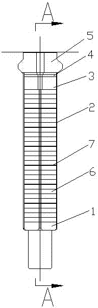
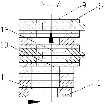
[0032] see figure 1 , a generator rotor ventilation slot structure, including slot bottom pads 1, rotor windings 2, under-wedge pads 3, damping windings 4 and rotor slot wedges 5, the rotor winding 2 consists of multiple copper bars 6 and inter-turn insulation 7 The copper bar 6 is formed by a plurality of copper wires 8 arranged side by side. The slot bottom pad 1, the rotor winding 2, the under-wedge pad 3, the damping winding 4 and the rotor slot wedge 5 are all provided with ventilation holes 9. In the axial direction of the rotor winding 2, there is a passage 10 which forms a radial ventilation with the ventilation hole 9, and any two adjacent copper bars 6 form the passage 10 in the axial direction of the rotor winding 2, and the entrance of the lower part of the passage 10 The tuyere 11 is arranged obliquely along the direction of the cooling air, and the upper part of the channel 10 is provided with an air channel 12 with an "S" shape in cross section, and the copper w...

Embodiment 2

[0035] see figure 2, a generator rotor ventilation slot structure, including slot bottom pads 1, rotor windings 2, under-wedge pads 3, damping windings 4 and rotor slot wedges 5, the rotor winding 2 consists of multiple copper bars 6 and inter-turn insulation 7 The copper bar 6 is formed by a plurality of copper wires 8 arranged side by side. The slot bottom pad 1, the rotor winding 2, the under-wedge pad 3, the damping winding 4 and the rotor slot wedge 5 are all provided with ventilation holes 9. In the axial direction of the rotor winding 2, there is a passage 10 which forms a radial ventilation with the ventilation hole 9, and any two adjacent copper bars 6 form the passage 10 in the axial direction of the rotor winding 2, and the entrance of the lower part of the passage 10 The tuyere 11 is arranged obliquely along the direction of the cooling air, and the upper part of the channel 10 is provided with an air channel 12 with an "S" shape in cross section, and the copper w...

Embodiment 3

[0039] see image 3 , a generator rotor ventilation slot structure, including slot bottom pads 1, rotor windings 2, under-wedge pads 3, damping windings 4 and rotor slot wedges 5, the rotor winding 2 consists of multiple copper bars 6 and inter-turn insulation 7 The copper bar 6 is formed by a plurality of copper wires 8 arranged side by side. The slot bottom pad 1, the rotor winding 2, the under-wedge pad 3, the damping winding 4 and the rotor slot wedge 5 are all provided with ventilation holes 9. In the axial direction of the rotor winding 2, there is a passage 10 which forms a radial ventilation with the ventilation hole 9, and any two adjacent copper bars 6 form the passage 10 in the axial direction of the rotor winding 2, and the entrance of the lower part of the passage 10 The tuyeres 11 are arranged obliquely along the direction of the cooling wind, and the upper part of the channel 10 is provided with three "S"-shaped air channels 12 in cross section, and the three "S...


PUM


Abstract

The invention discloses a ventilating slot structure of a generator rotor. The ventilating slot structure of the generator rotor comprises a slot bottom filler strip, a rotor winding, a filler strip under a wedge, a damping winding and a rotor slot wedge, wherein at least one channel forming radial ventilating with a vent hole is axially formed in the rotor winding, any two adjacent copper rows form the channel in the axial direction of the rotor winding, an air inlet in the lower part of the channel is slantly distributed in the direction of cooling air, a ventilating duct with an S-shaped cross section is at least arranged at the upper part of the channel, a plurality of copper wires in the axial direction of the copper rows at the upper part of the channel are distributed in a staggered manner, and any two adjacent copper rows form the S-shaped vent duct in the axial direction of the rotor winding. The air inlet in the lower part of the channel is slantly distributed in the direction of the cooling air, so that the air intake resistance of the air inlet of the channel is effectively reduced, the air intake flow rate of the cooling air entering the channel is increased, the cooling air entering through the air inlet in the lower part of the channel enters the S-shaped vent duct to form turbulent flow, so that the ventilating and cooling effects are greatly improved.

Description

technical field [0001] The invention relates to the technical field of generators, in particular to a generator rotor ventilation groove structure. Background technique [0002] A generator is a mechanical device that converts other forms of energy into electrical energy. It is driven by a water turbine, steam turbine, diesel engine or other power machinery, and converts the energy generated by water flow, air flow, fuel combustion or nuclear fission into mechanical energy and transmits it to the generator. Converted to electrical energy by a generator. Generators are widely used in industrial and agricultural production, national defense, science and technology and daily life. There are many forms of generators, but their working principles are all based on the law of electromagnetic induction and the law of electromagnetic force. Therefore, the general principle of its construction is: use appropriate magnetic and conductive materials to form magnetic circuits and circui...

Claims


Application Information

Patent Timeline
Patent Type & Authority Patents(China)
IPC IPC(8): H02K3/24H02K1/32
CPCH02K1/32H02K3/24
Inventor 胡德剑王建立王黔杨国龙冯天福
Owner DONGFANG ELECTRIC MACHINERY
Why Eureka
Try Eureka