
Method for operating a wheel slip control apparatus with compensated wheel speeds

A technology for adjusting devices and wheels, which is applied in transportation and packaging, control/regulation systems, vehicle components, etc., and can solve the problem that the wheel speed difference is no longer accurately compensated

Active Publication Date: 2015-03-11
KNORR BREMSE SYST FUER NUTZFAHRZEUGE GMBH
View PDF7 Cites 17 Cited by
  • Summary
  • Abstract
  • Description
  • Claims
  • Application Information

AI Technical Summary

Problems solved by technology

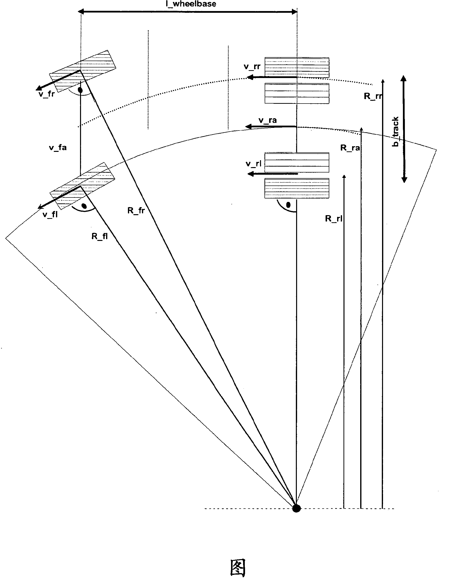
[0004] However, if the turning radius changes during braking, for example if the driver changes the steering angle while the vehicle is already turning, the rotational speed difference between the wheels is no longer exactly compensated

Method used


Image

  • Method for operating a wheel slip control apparatus with compensated wheel speeds
  • Method for operating a wheel slip control apparatus with compensated wheel speeds
  • Method for operating a wheel slip control apparatus with compensated wheel speeds

Examples


Embodiment Construction

[0038]The method according to the invention is carried out within the scope of a wheel slip control device such as ABS (anti-lock brake system) or ASR (drive anti-skid system), which method converts the brake slip and / or The drive slip rate is adjusted or limited to the optimum slip rate. The wheel slip control system is integrated in the driving dynamics control system, such as ESP (Electronic Stability Program).

[0039] Steering angle δ from the steering angle sensor, actual-yaw rate ω from the yaw rate detection device z_meas And the vehicle speed v from the wheel speed sensor is provided as sensor information to the controller of the driving dynamics control device. The reference yaw rate ω is also calculated in the controller of the driving dynamics control on the basis of the steering angle δ and the vehicle speed v z_ref , the reference-yaw rate is the target-yaw rate desired by the driver.

[0040] By means of the method described below, a compensated wheel speed i...


PUM


Abstract

The invention relates to a method for operating a wheel slip control apparatus of a vehicle, including determining wheel speeds (Vfl_C, Vfr_C, Vrr_C, Vrl_C) of wheels of the vehicle as input variables for the wheel slip control apparatus, said wheel speeds being compensated for in terms of wheel speed differences during travel around curves, wherein: a) a neutral-steering, understeering or oversteering driving condition of the vehicle is determined from the driving characteristics of said vehicle during travel around curves; b) based on the determined neutral-steering, understeering or oversteering driving condition of said vehicle, either the reference yaw rate (omegaz_ ref) or the actual yaw rate (omegaz_meas) is used for calculating a curve radius (Rra_ref or Rra_meas) related to a selected point on said vehicle; c) wheel-related curve radii (Rrl, Rrr, Rfl, Rfr) for at least some of said wheels of said vehicle are determined from said curve radius (Rra_ref or Rra_meas) related to the selected point; d) reference factors (kfl, kfr, krl, krr) are determined from said wheel-related curve radii (Rrl, Rrr, Rfl, Rfr) and a common reference curve radius (Rra) for the at least some of said wheels of said vehicle; e) the compensated wheel speeds (Vfl_C, Vfr_C, Vrr_C, Vrl_C) are determined in each case from said reference factors (kfl, kfr, krl, krr) and measured wheel speeds (Vrl, Vrr, Vfl, Vfr) for the at least some of said wheels of said vehicle, and f) for the at least some of said wheels of said vehicle said compensated wheel speeds (Vfl_C, Vfr_C, Vrr_C, Vrl_C) are used as input variables for said wheel slip control apparatus.

Description

technical field [0001] The invention relates to a method for operating a wheel slip control device of a vehicle according to the preamble of claim 1 , the method comprising determining the wheel speeds of the vehicle wheels which are compensated for the difference in wheel speed when cornering as a means for Input variables of the wheel slip control device; and the invention relates to a wheel slip control device according to claim 9 which is operated according to the method. Furthermore, the invention relates to a driving dynamics control device according to claim 10 including such a wheel slip control device. Background technique [0002] The aim of wheel slip control devices such as ABS (Antilock Braking System) or ASR (Actuation Anti-Slip System) is to adjust or limit the braking slip or drive slip occurring on the wheels to an optimum slip Rate. The optimal brake slip is, for example, 12%. The wheel slip is determined by comparing the wheel speed of the concerned whe...

Claims


Application Information

Patent Timeline
Patent Type & Authority Applications(China)
IPC IPC(8): B60T8/172B60T8/1761B60T8/1755
CPCB60T8/17551B60T8/17616B60T8/172B60T2201/16B60T2210/24B60T8/1761B60T2230/00B60T2240/00B60T2250/00B60T2270/12B60T2270/202B60T8/171B60T8/175B60T8/17552B60T2230/02B60W2510/207G05D13/66G05D15/00
Inventor M·沃雷特尔
Owner KNORR BREMSE SYST FUER NUTZFAHRZEUGE GMBH
Learn More