Flue gas desulfurization method and flue gas desulfurization device

A desulfurization device, flue gas technology, applied in separation methods, chemical instruments and methods, dispersed particle separation, etc., can solve the problems of complex process, poor adjustment accuracy, slow response speed, etc., to meet the control objectives, fast response speed, The effect of accurate feedback measurements

Inactive Publication Date: 2015-10-21
苏跃进
View PDF5 Cites 7 Cited by
  • Summary
  • Abstract
  • Description
  • Claims
  • Application Information

AI Technical Summary

Problems solved by technology

[0005] The purpose of the present invention is to provide a flue gas desulfurization method, which solves the problems of complex process, slow response speed and poor adjustment accuracy of the existing process for adjusting the real-time sulfur dioxide concentration of outlet flue gas

Method used


Image

  • Flue gas desulfurization method and flue gas desulfurization device
  • Flue gas desulfurization method and flue gas desulfurization device
  • Flue gas desulfurization method and flue gas desulfurization device

Examples


Embodiment 1

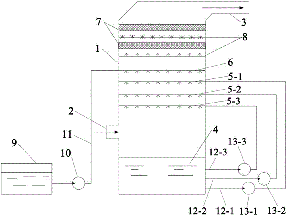
[0037] The flue gas desulfurization device of this embodiment, such as figure 1 As shown, it includes a desulfurization tower 1 and a limestone slurry pool 9 for preparing newly supplemented limestone slurry. The lower part of the desulfurization tower 1 is provided with a flue gas inlet 2 and the upper part is provided with a flue gas outlet 3. The inner flue gas inlet 2 of the desulfurization tower 1 is There is a circulating slurry pool 4 under the desulfurization tower 1, and there are three circulating slurry spray layers between the flue gas inlet 2 and the flue gas outlet 3 in the desulfurization tower 1, which are used to spray the circulating desulfurization slurry into the desulfurization tower 1, from top to bottom The first spray layer 5-1, the second spray layer 5-2 and the third spray layer 5-3; the first spray layer 5-1, the second spray layer 5-2 and the third spray layer Layer 5-3 communicates with the circulating slurry pool 4 through circulating pipelines 12...

Embodiment 2

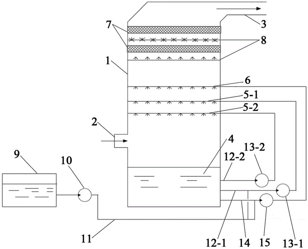
[0042] The flue gas desulfurization device of this embodiment, such as figure 2 As shown, the difference from Example 1 is that: the desulfurization tower 1 is provided with two layers of circulating slurry spray layers for spraying the circulating desulfurization slurry into the desulfurization tower 1 between the flue gas inlet 2 and the flue gas outlet 3. From top to bottom are the first spray layer 5-1 and the second spray layer 5-2;

[0043] The limestone slurry pipeline 11 is connected with a connecting pipeline 14 between the limestone slurry pump 10 and the highest spray layer 6, and the other end of the connecting pipeline 14 communicates with the circulating slurry pool 4; the limestone slurry pipeline 11 A slurry circulation pump 15 is provided between the connection with the connecting pipeline 14 and the highest spray layer, for transporting the circulating slurry in the circulating slurry pool 4 to the highest spray layer 6; A spray layer 5-1 is the second high...

Embodiment 3

[0046] The flue gas desulfurization method of this embodiment includes spraying newly supplemented limestone slurry into the desulfurization tower through the highest spray layer of the desulfurization tower; by adjusting the concentration and injection flow rate of the newly supplemented limestone slurry, controlling the flow rate of the flue gas at the outlet of the desulfurization tower Sulfur dioxide concentration.

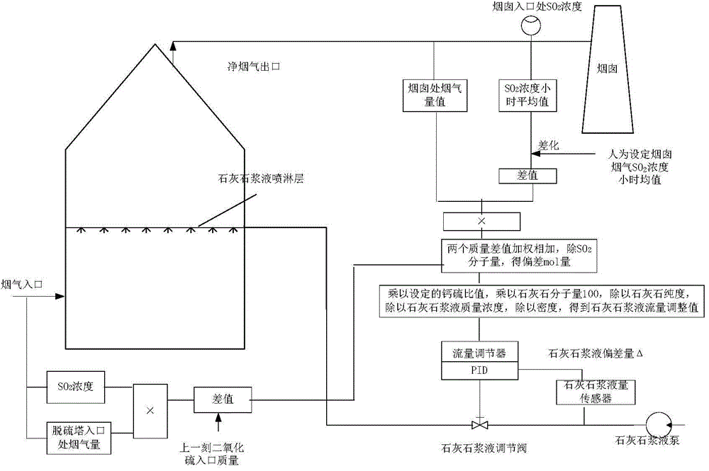
[0047] Adopt the flue gas desulfurization device of embodiment 1 to realize above-mentioned flue gas desulfurization method, the method for adjusting the concentration of the newly replenished limestone slurry and the injection flow rate specifically comprises the following steps (the principle of the control process is as follows: image 3 shown):

[0048] 1) Set the target control value of sulfur dioxide concentration in the outlet flue gas according to the externally assessed flue gas outlet sulfur dioxide concentration value (the hourly average value of th...


PUM


Abstract

The invention discloses a flue gas desulfurization method and a flue gas desulfurization device. The flue gas desulfurization method comprises the following steps: spraying newly supplemented desulfurizing agent slurry into a desulfurizing tower through the highest spray level of the desulfurizing tower; controlling the sulfur dioxide concentration of the flue gas at the outlet of the desulfurizing tower through adjusting the concentration and / or the spray flow of the newly supplemented desulfurizing agent slurry. According to the flue gas desulfurization method, the newly supplemented desulfurizing agent slurry is sprayed into the desulfurizing tower through the highest spray level of the desulfurizing tower, and the characteristic that the capability of the newly supplemented desulfurizing agent slurry to absorb low-concentration sulfur dioxide in flue gas is far higher than that of a circulating desulfurization slurry with relatively low pH value as the pH value of the newly supplemented desulfurizing agent slurry is far higher than that of the circulating desulfurization slurry is fully utilized, so that the sulfur dioxide concentration of the flue gas at the outlet of the desulfurizing tower can be quickly adjusted; the method directly responses to the target concentration value of the flue gas at the outlet of the desulfurizing tower, and has the advantages of being high in response speed, high in adjustment precision and good in adjustment quality.

Description

technical field [0001] The invention belongs to the technical field of flue gas desulfurization, and in particular relates to a flue gas desulfurization method and also relates to a flue gas desulfurization device. Background technique [0002] Flue Gas Desulfuration (FGD) refers to the removal of sulfur oxides (mainly SO 2 and SO 3 )the process of. The sulfur oxides in the flue gas are acidic in nature and can be removed from the flue gas by reacting with appropriate alkaline substances to form a mixture of sulfite and sulfate. The most commonly used alkaline substances for flue gas desulfurization are limestone (calcium carbonate), quicklime (calcium oxide) and slaked lime (calcium hydroxide). Limestone is abundant and relatively cheap. Both quicklime and slaked lime are produced by heating limestone. [0003] Limestone / lime-gypsum wet desulfurization process is currently the most widely used desulfurization process. This process mainly uses cheap and easy-to-obtain li...

Claims


Application Information

Patent Timeline
IPC IPC(8): B01D53/80B01D53/50B01D53/96
Inventor 苏跃进
Owner 苏跃进
Why Eureka
Try Eureka