Clamping unit for containers on container handling machines

一种处理装置、容器的技术,应用在标记非刚性容器、包装、运输和包装等方向,能够解决竖直位置依赖等问题

Active Publication Date: 2015-03-18
KRONES AG
View PDF8 Cites 22 Cited by
  • Summary
  • Abstract
  • Description
  • Claims
  • Application Information

AI Technical Summary

Problems solved by technology

Another disadvantage is that the vertical position of the centering support depends on the current position of the respective clamping unit in a segment of the stroke curve

Method used


Image

  • Clamping unit for containers on container handling machines
  • Clamping unit for containers on container handling machines

Examples


Embodiment Construction

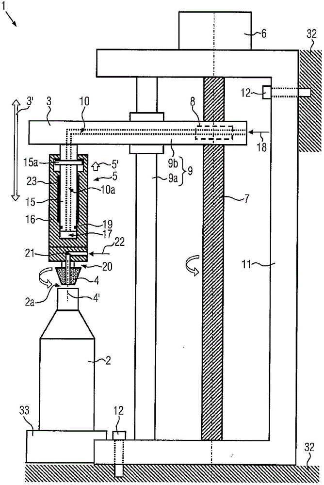
[0024] Such as figure 1 As shown, a preferred embodiment of the gripping unit 1 of the invention for a container 2 comprises a lifting arm 3 which is displaceable in a vertical direction 3', in particular linearly in a vertical direction 3', The lifting arm 3 carries a centering support 4 , which preferably rotates about an axis 4 ′, by means of which the container 2 can be gripped from above. For example, the centering support 4 cooperates with the mouth area 2 a of the container 2 . The centering support 4 may also have a bell-like design in order to grip a closed container from above by holding it from the outside (not shown).

[0025] The centering support 4 is elastically mounted at the lifting arm 3 in the vertical direction by means of a pneumatic spring 5 . From figure 1 From the shown rest position of the centering support 4 not in contact with the container 2 , the centering support 4 can perform a relative movement upwards relative to the lifting arm 3 against th...


PUM


Abstract

A clamping unit for containers at container treatment machines where, apart from a vertically movable lifting arm with a centering support for clamping a container from above, a motor for driving the lifting arm and a pneumatic spring against the resistance of which the centering support is mounted at the lifting arm so as to be movable to the top are provided. The lifting arms may be set to a desired vertical position independently of the movement or the rotational position of an associated rotary machine, and a clamping force of the centering supports may be easily and flexibly adjusted by applying a suited pressure to the pneumatic spring.

Description

technical field [0001] The invention relates to a gripping unit for containers at a container handling device and to a container handling device having several gripping units according to the invention, in particular for direct printing on containers. Background technique [0002] During processing in container handling machines, especially in rotary machines such as labeling or printing, containers such as beverage bottles are usually held in circumferentially evenly distributed gripping units on a turntable, which is held by Drive continuously or discontinuously. In order to adjust the rotational position of the containers relative to the circular path of the turntable, preferably the containers are loaded on the turntable and pressed down in the mouth area or closure area by a centering support such as a centering bell. On the other hand, care needs to be taken here that the clamping force is sufficiently high to ensure that the container remains in place in the clamping...

Claims


Application Information

Patent Timeline
Patent Type & Authority Applications(China)
IPC IPC(8): B41J3/407B65C9/06B65C9/04
CPCB65C9/04B65G47/847B65C3/26B41J3/4073B41J3/40733
Inventor 奥古斯特·派特安德鲁斯·克劳斯
Owner KRONES AG
Why Eureka
Try Eureka