

Beverage container
A beverage and container technology, used in applications, heat-insulating utensils, household appliances, etc., can solve the problems of long operating distance, wear of blocking parts, troublesome operation, etc., and achieve the effect of firm water-stopping, restraining rising, and preventing spraying
- Summary
- Abstract
- Description
- Claims
- Application Information
AI Technical Summary
Problems solved by technology
Method used
Image

Examples
Embodiment 1
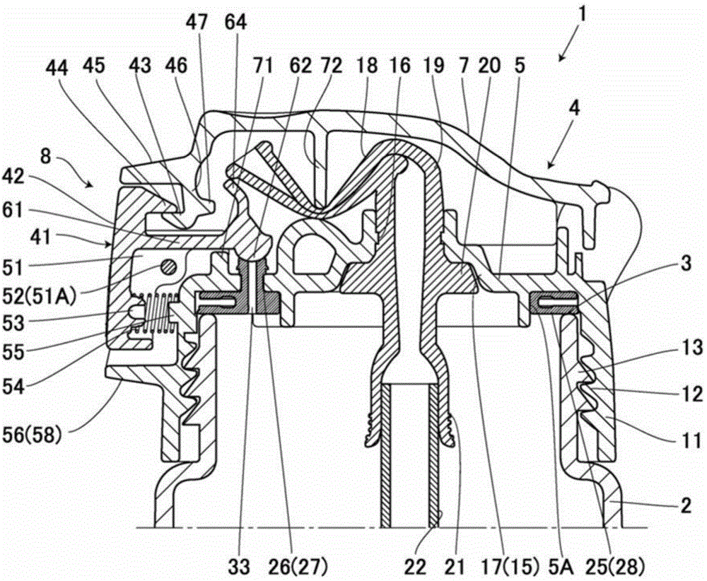
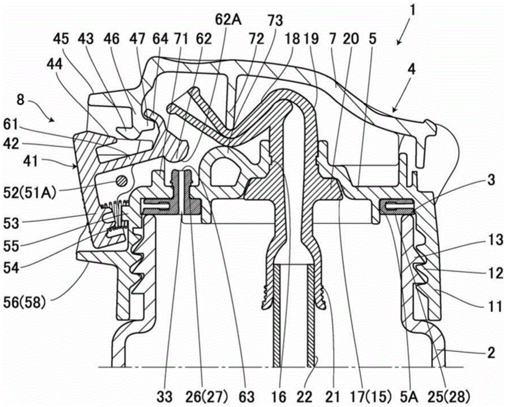
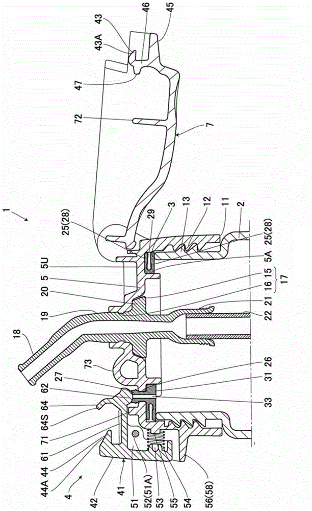
[0055] exist Figure 1 to Figure 8 , reference numeral 1 denotes a beverage container. The beverage container 1 includes a metal or synthetic resin container body 2 and a synthetic resin plug 4 covering the container opening 3 which is an upper opening of the container body 2 . The cup-shaped cover body 7 passes through the hinge shaft 6 (refer to Figure 6 ) can be freely opened and closed, and the cover body 7 can be kept in a closed state by the locking mechanism 8 provided on the opposite side of the hinge shaft 6 ( figure 1 ).
[0056] The above-mentioned plug body 4 has a plug body body 11 formed in an inverted bottomed cylindrical shape provided with a top portion 5 covering the upper opening of the container body 2 . The cap body 4 can be screw-fitted to a cylindrical male thread portion 13 provided on the upper outer peripheral surface of the container body 2 via the female thread portion 12 formed on the inner peripheral surface of the plug body body 11 .
[0057...
Embodiment 2
[0103] Figure 9 ~ Figure 12 A beverage container according to Example 2 of the present invention is shown. exist Figure 9 ~ Figure 12 In , the same reference numerals are assigned to the same parts as those in the first embodiment described above, and detailed description thereof will be omitted.
[0104] In this embodiment, a valve communication portion 81 is provided on the top portion 5 of the plug body 4 , and a valve 85 is detachably attached to the valve communication portion 81 from below.
[0105] In addition, in this figure, the inner locking piece 47 and the inner locking portion 64 are not provided, but the inner locking piece 47 and the inner locking portion 64 may be provided in the same manner as in the first embodiment.
[0106] The valve communication portion 81 includes a circular through-hole 82 formed through the top portion 5 , and suction holes 83 , 83 formed in a slit shape outward from the through-hole 82 . The suction holes 83 and 83 are provided o...
Embodiment 3
[0111] Figure 13 A beverage container according to Example 3 of the present invention is shown. exist Figure 13 In , the same reference numerals are assigned to the same parts as those in the first embodiment described above, and detailed description thereof will be omitted.
[0112] In this embodiment, the suction pipe unit 19 and the cylindrical protrusion 27 are connected by the plate-shaped connection part 91 . Furthermore, the connecting portion 91 is also formed of an elastic member such as silicone rubber or elastomer resin.
[0113] In addition, as described above, in the beverage container of this embodiment, the vent hole 33 as the communicating portion and the straw unit 19 as the spout member are integrated, so the number of parts can be reduced.
PUM
 Abstract
Description
Claims
Application Information