Supercharge Your Innovation With Domain-Expert AI Agents!

Linear motion device

A technology of linear motion and sliding parts, which is applied in the direction of transmission devices, belts/chains/gears, mechanical equipment, etc., can solve problems such as loss of position, achieve the effect of simplifying assembly and improving adjustment accuracy

Active Publication Date: 2015-03-18
ROBERT BOSCH GMBH
View PDF7 Cites 6 Cited by
  • Summary
  • Abstract
  • Description
  • Claims
  • Application Information

AI Technical Summary

Problems solved by technology

[0006] The disadvantage of this linear motion device is that the adjustment of the radial distance via the movement of the wedge-shaped slats can only be carried out relatively roughly, and between the positioning of the wedge-shaped slats by the fitter and the fixing of the slide with screws, there will be lost position again

Method used


Image

  • Linear motion device
  • Linear motion device
  • Linear motion device

Examples


Embodiment Construction

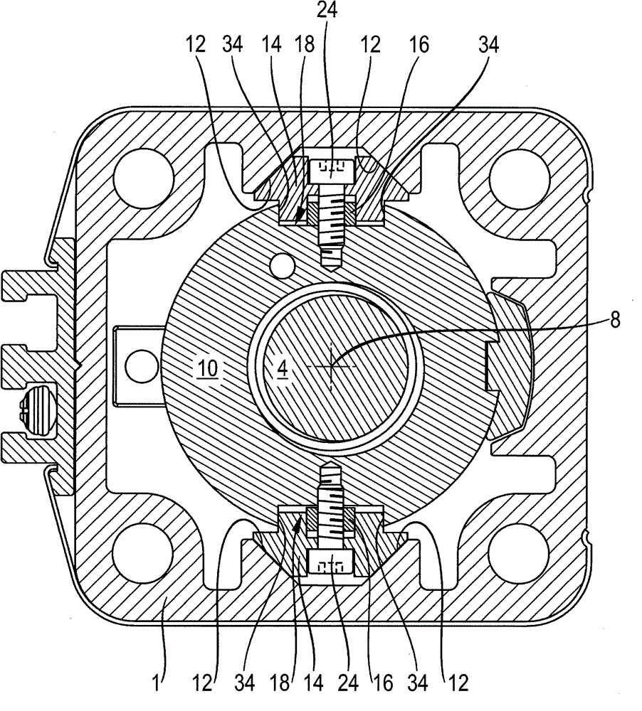
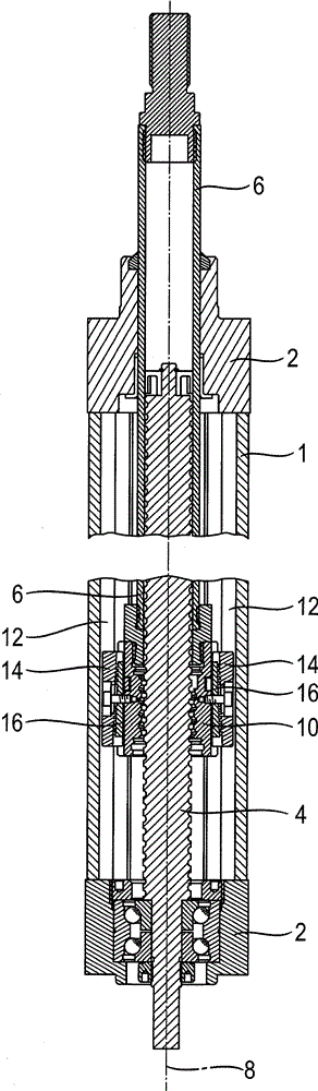
[0028] figure 1 An embodiment of the linear motion device according to the invention is shown in a side sectional view. It has an approximately square, elongated housing 1 in cross section, which is closed at the end faces by means of two caps 2 . exist figure 1 The end section of a threaded spindle 4 is supported in the lower cover 2 via a rolling bearing, and in figure 1 A cantilever 6 movable relative to the housing 1 is slidably supported in the upper cover 2 in the middle. exist figure 1 The upper end section of the cantilever 6 protrudes from the housing 1 . A device (not shown) which is to move along the longitudinal axis 8 of the linear movement device can be coupled to this end section.

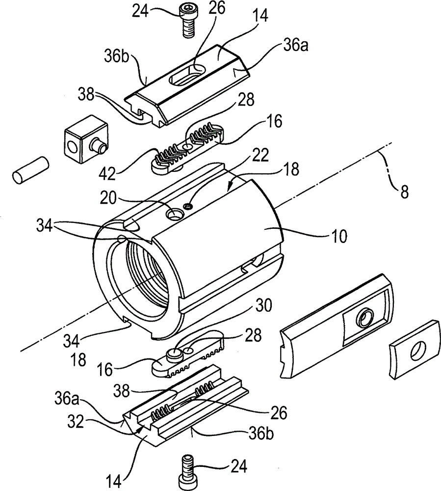
[0029] exist figure 1 The lower end section of the cantilever arm 6 is fastened to a spindle nut 10 which is slidably supported in the housing 1 . The spindle nut 10 and the threaded spindle 4 are in active engagement with each other via a row of annularly encircling balls (no...


PUM


Abstract

The invention relates to a spindle drive device, having a housing at a fixed position, in which a threaded spindle is rotatably supported, whereby a lift rod can move out of the housing to different extent depending on the operating state. The movement is along the longitudinal axis of the spindle drive device. The lift rod is fastened to a spindle nut, which engages with the threaded spindle. Two slide laths are fastened on the outer circumference of the spindle nut and are used as anti relative rotation members to guide, in a groove extending correspondingly parallel to the longitudinal axis, of the housing. A wedge lath is inserted between each slide lath and the spindle nut, and has a thickness parallel to the direction of the longitudinal axis. Abutting portions of the two slide laths and the two mating wedge laths are provided with corresponding grooves, through which the shape locking between the wedge laths and the slide laths along the longitudinal axis is formed. Therefore, the radial gas between the two slide laths in the housing can be simply and finely (stepwise) adjusted through the movement of the corresponding wedge laths.

Description

technical field [0001] The invention relates to a linear motion device or a linear drive according to the preamble of claim 1 . Background technique [0002] Conventional linear motion devices are designed as spindle drives and have a threaded spindle mounted rotatably about a longitudinal axis in a housing, which engages in the housing with a spindle nut displaceable in the direction of the longitudinal axis. A lifting rod penetrating through the housing is fastened to the spindle nut, into which the threaded spindle is immersed more or less deeply, depending on the operating state of the linear motion device. The lifting rod is coupled via an articulation point remote from the thread spindle to a further device to be moved or supported. [0003] Such a linear motion device is also called an electric cylinder, since the housing resembles a hydraulic cylinder and the lifting rod resembles a piston rod in terms of usability and appearance. Of course, instead of a pressure m...

Claims


Application Information

Patent Timeline
Patent Type & Authority Applications(China)
IPC IPC(8): F16H25/20
CPCF16H25/20F16H2025/204F16H25/2003
Inventor P.施莱格尔
Owner ROBERT BOSCH GMBH
Features
  • R&D
  • Intellectual Property
  • Life Sciences
  • Materials
  • Tech Scout
  • Unparalleled Data Quality
  • Higher Quality Content
  • 60% Fewer Hallucinations
Learn More