Air conditioner indoor unit and air conditioner

A technology of air conditioner and indoor unit, applied in the direction of control input related to air characteristics, air conditioning system, space heating and ventilation details, etc., which can solve problems such as condensation

Active Publication Date: 2015-03-18
HITACHI JOHNSON CONTROLS AIR CONDITIONING INC
View PDF5 Cites 6 Cited by
  • Summary
  • Abstract
  • Description
  • Claims
  • Application Information

AI Technical Summary

Problems solved by technology

[0006] However, in the air conditioner of Patent Document 1, during the normal cooling operation mode, the high-temperature and humid indoor air and the low-temperature discharge air are separated by the lower vertical louver, and air flow is carried out from the back of the lower vertical louver to the front. Condensation occurs on the surface side of the lower vertical louver exposed to high temperature and humidity indoor air due to heat conduction

Method used


Image

  • Air conditioner indoor unit and air conditioner
  • Air conditioner indoor unit and air conditioner
  • Air conditioner indoor unit and air conditioner

Examples


no. 1 approach

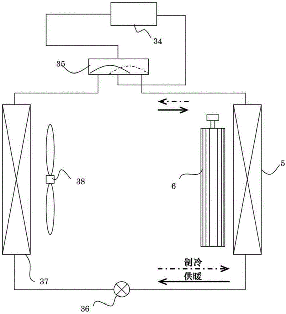
[0064] figure 1 It is a cycle configuration diagram of the air conditioner of the first embodiment. During the cooling operation, the high-temperature and high-pressure refrigerant discharged from the compressor 34 flows into the outdoor heat exchanger 37 through the four-way valve 35 . The refrigerant flowing into the outdoor heat exchanger 37 exchanges heat with the outdoor air sent by the outdoor blower fan 38 , and is condensed to become a liquid refrigerant. The liquid refrigerant passes through the expansion valve 36 to become a low-temperature and low-pressure two-phase refrigerant, and flows into the indoor heat exchanger 5 . The low-temperature and low-pressure two-phase refrigerant flowing into the indoor heat exchanger 5 exchanges heat with the indoor air sent by the indoor blower fan 6 . At this time, the indoor air sent to the indoor heat exchanger 5 is cooled by the low-temperature and low-pressure two-phase refrigerant flowing into the indoor heat exchanger 5 ...

no. 2 approach

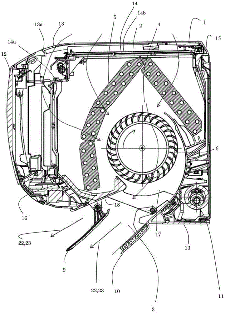
[0097] The second embodiment differs from the first embodiment in that the lower case 11 of the second embodiment has a first inclined portion 29 and a second inclined portion located on the downstream side (front end side) of the first inclined portion 29 . Section 30. The second inclined portion 30 is inclined toward the floor surface on the front end side compared with the first inclined portion 29 .

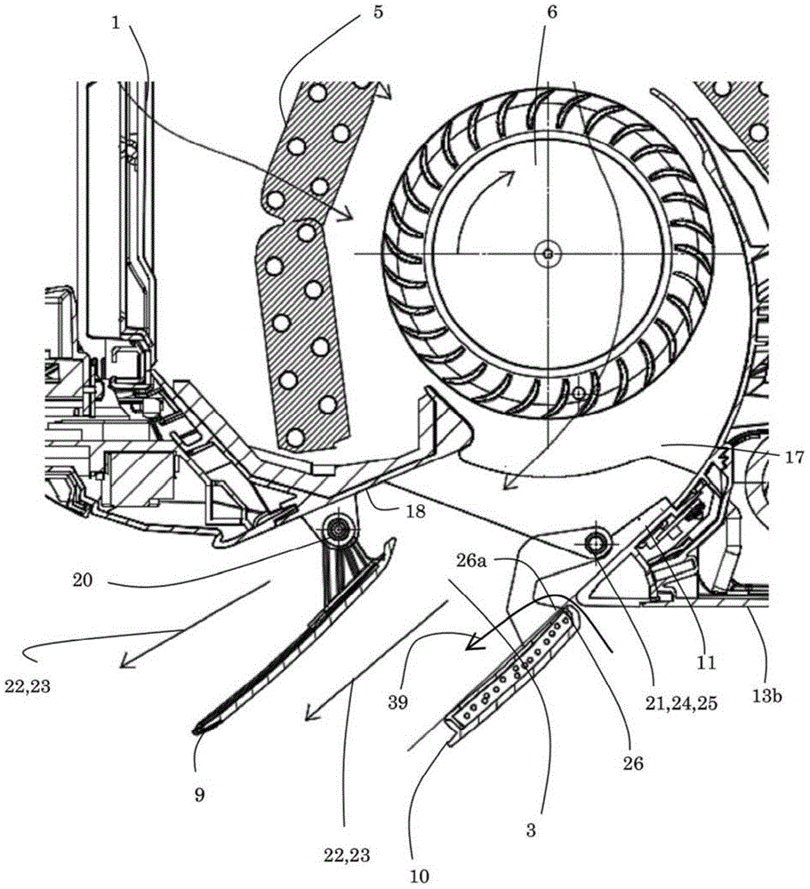
[0098] Next, use Figure 6 to Figure 8 The operation of the vertical louver of the second embodiment will be described. Figure 6 It is an enlarged side sectional view of the air outlet of the indoor unit in the capacity priority mode of the second embodiment. In the capacity priority mode, the lower vertical louver 10 is rotated around the shaft 21 of the lower vertical louver so that the upper surface of the lower vertical louver 10 is positioned at the first inclined portion of the lower housing 11 29 or located below the extension line of the lower case. As a result, ...


PUM


Abstract

The invention aims to provide an air conditioner indoor unit which has high blast efficiency and meanwhile can restrain moisture condensation of upper and lower wind plates, and an air conditioner. The air conditioner has a capacity-based-priority mode in which an upper surface in an upstream side end portion of upper and lower wind plates on lower sides is located on an extension cord of a lower side housing or at a position lower than the extension cord of a lower side housing, and a general refrigeration operation mode in which the upper surface in the upstream side end portion of upper and lower wind plates on lower sides is located at a position higher than the extension cord of the lower side housing. The distance between the upper and lower wind plates on lower sides and the lower side housing in the general refrigeration operation mode is longer than the distance between the upper and lower wind plates on lower sides and the lower side housing in the capacity-based-priority mode.

Description

technical field [0001] The invention relates to an indoor unit of an air conditioner and an air conditioner. Background technique [0002] Patent Document 1 discloses an air conditioner in which a lower vertical louver is arranged substantially on an extension line of a lower casing, and the lower casing and one end of the lower vertical louver are arranged almost without a gap. Therefore, the blown air is not easy to leak from the close part, thereby avoiding the reduction of the efficiency of blowing. [0003] 【Prior technical literature】 [0004] 【Patent Literature】 [0005] [Patent Document 1] Japanese Patent Application Laid-Open No. 9-287807 [0006] However, in the air conditioner of Patent Document 1, during the normal cooling operation mode, the high-temperature and humid indoor air and the low-temperature discharge air are separated by the lower vertical louver, and air flow is carried out from the back of the lower vertical louver to the front. Due to heat con...

Claims


Application Information

Patent Timeline
Patent Type & Authority Applications(China)
IPC IPC(8): F24F1/00F24F13/08
CPCF24F1/00F24F11/30F24F13/1413F24F13/20F24F2013/1433F24F2110/20
Inventor 村若正俊大乡贤一大馆一夫
Owner HITACHI JOHNSON CONTROLS AIR CONDITIONING INC
Why Eureka
Try Eureka