Special timing power strip for charging battery car
What is Al technical title?
Al technical title is built by PatSnap Al team. It summarizes the technical point description of the patent document.
A technology for power strips and battery cars, which is applied to circuits, electrical components, vehicle connectors, etc. It can solve the problems of not being able to automatically cut off the power, more than ten small parts overnight, expansion and deformation of the outer shell, and shortened life. It achieves high cost performance, The effect of prolonging life and prolonging service life
Inactive Publication Date: 2015-03-18
刘品华
View PDF1 Cites 1 Cited by
Summary
Abstract
Description
Claims
Application Information
AI Technical Summary
This helps you quickly interpret patents by identifying the three key elements:
Problems solved by technology
Method used
Benefits of technology
Problems solved by technology
[0002] At present, the charging of the battery car is to connect the charger and plug in the AC power supply at night to start charging. The power is cut off and the charging is stopped until the next morning when the car is used. In fact, the battery is not completely used up every time it is charged, and there may be half of it. Electricity, in order to avoid insufficient electricity tomorrow, it has to be recharged. It only takes 3-4 hours to replenish the electricity. However, the battery cannot be automatically cut off at night when the battery is fully charged. This will cause outdated charging for more than ten hours a night. In summer, it will be converted by electric energy. The battery is always heating during the process of chemical energy. When the voltage is charged to 58V, the red light turns to green light. At this time, the internal temperature of the battery has reached the highest value and produces high voltage. If you continue to recharge, the outer shell will expand and deform. It will also cause rapid aging of the active materials on the internal positive and negative plates due to excessive high-temperature chemical reactions and shorten their lifespan.
Method used
Image
Click on the blue label to locate the original text in one second.
Reading with bidirectional positioning of images and text.
Examples
Embodiment Construction
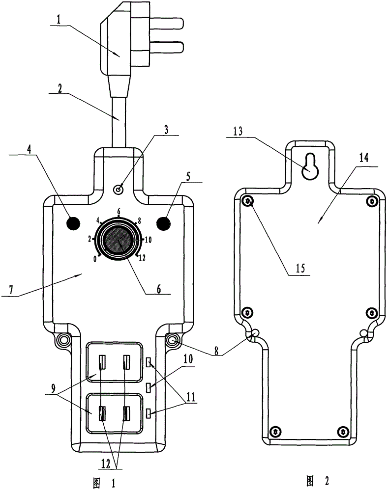
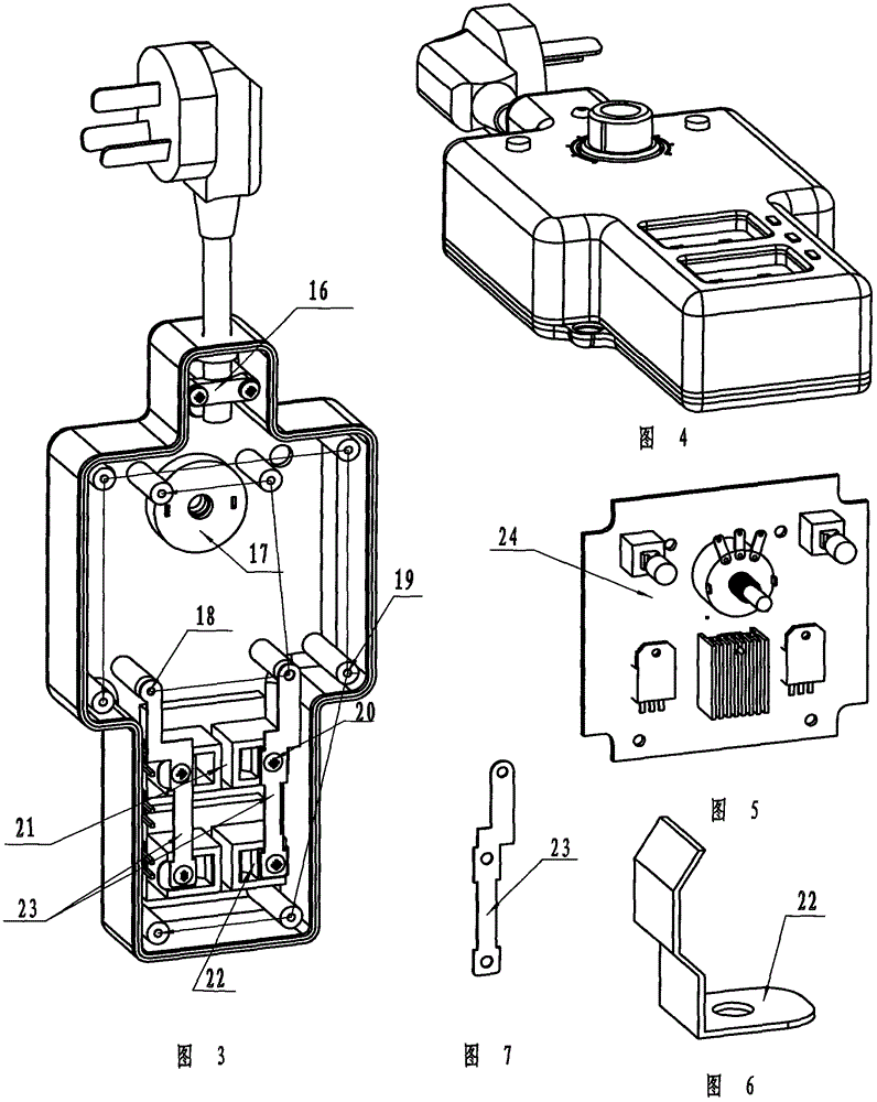
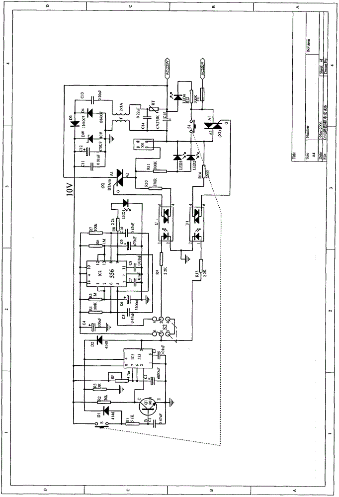
[0021] One end of the power cord (2) is connected to the power plug (1), and the other end extends into the front shell (7) of the plug-in main body to connect with the circuit board (24). The circuit board (24) is put into the inner upper part of the front shell (7) of the plug-in main body, and is fixed on the circuit board fixing pile (18) with 4 self-tapping screws, and the clamp (22) is inserted into the square hole slot ( 21), press the connecting piece (23) on the top of the clamping piece (22), connect the upper end with the circuit board (24), fix it with the clamping screw (20), and put two red and one green three The LED diodes are inserted into the three fixing holes, and are connected to the circuit board through the connector wires, and finally the rear cover is installed on the front shell (7) of the main body of the plug-in strip using fastening screws (15) and rear cover fixing piles (19). ) to fix, and then install the timing knob (6) to complete. Circuit sc...
PUM
Abstract
The invention discloses a special timing power strip for charging a battery car, and belongs to the field of battery charging. A power plug (1), a power line (2), an AC power indicating lamp (3), a mode button (4), a starting button (5), a timing button (6), a power strip main body front shell (7), fixing screw holes (8), grooves (9), an interval green indicating lamp (10), red charging indicating lamps (11), power jacks (12), a wall screw hole (13), a rear socket cover plate (14), fastening screws (15), a wire pressing pipe clamp (16), a concave-convex groove (17), circuit board fixing piles (18), rear cover plate fixing piles (19), clamp screws (20), square hole grooves (21), clamping parts (22), connecting parts (23) and a circuit board (24) are connected to form a timing and cyclic timing charging device. The special timing power strip has the following three major advantages: firstly, a battery can be charged both in a timing mode and a cyclic timing mode and power can be compensated according to real power deficiency in a time-limit mode; secondly, aging of a polar plate is greatly delayed and the service life of the battery is prolonged; and thirdly, the power strip and a charger are synchronously powered on and self-locked and are automatically cut off when charging is finished, thus saving power and prolonging the service life of the power strip and the charger.
Description
technical field [0001] The present invention relates to a special timing power strip for charging in the field of battery charging. The power strip can automatically charge the battery within a time limit, and has two charging modes: regular charging and cycle timing charging. After the timing charging is completed, not only It can automatically cut off the AC power of the charger, and at the same time cut off the AC power of the plug strip itself, so as to realize zero loss of electric energy, effectively prevent the battery from being damaged due to overcharging, causing the battery car to self-burn and destroy, causing safety accidents, causing Economic losses, but also save electricity. Background technique [0002] At present, the charging of the battery car is to connect the charger to the AC power supply at night to start charging, and the power is cut off and the charging is stopped until the next morning when the car is used. In fact, the battery is not completely u...
Claims
Application Information
Patent Timeline
Application Date:The date an application was filed.
Publication Date:The date a patent or application was officially published.
First Publication Date:The earliest publication date of a patent with the same application number.
Issue Date:Publication date of the patent grant document.
PCT Entry Date:The Entry date of PCT National Phase.
Estimated Expiry Date:The statutory expiry date of a patent right according to the Patent Law, and it is the longest term of protection that the patent right can achieve without the termination of the patent right due to other reasons(Term extension factor has been taken into account ).
Invalid Date:Actual expiry date is based on effective date or publication date of legal transaction data of invalid patent.