Permanent magnet-type electric motor, compressor and refrigeration cycle device using the same
A refrigeration cycle and motor technology, which is applied to electromechanical devices, electric components, magnetic circuit rotating parts, etc., can solve problems such as forming/processing difficulties, and achieve the effects of improving efficiency, suppressing magnetic flux leakage, and improving torque
- Summary
- Abstract
- Description
- Claims
- Application Information
AI Technical Summary
Problems solved by technology
Method used
Image

Examples
Embodiment 1
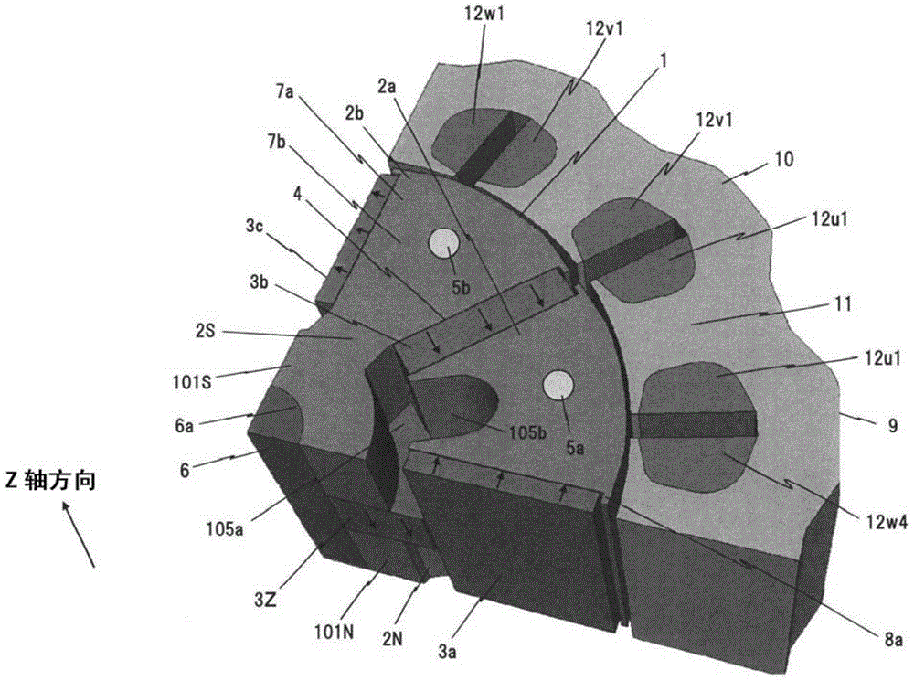
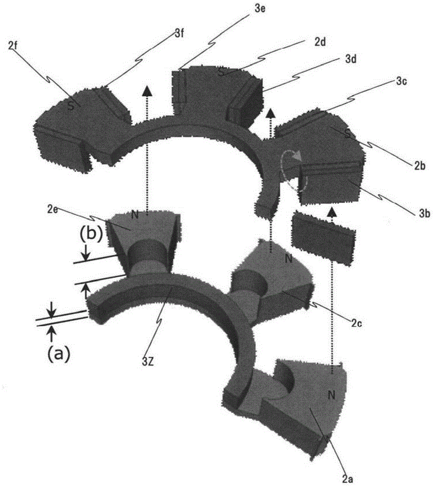
[0039] Below, use Figure 1 ~ Figure 4 A first embodiment of the present invention will be described. figure 1 It is a figure which stereoscopically shows the circumferential 1 / 4 part of the stator and the rotor of the permanent magnet motor in this Example. Figure 2 is for figure 1 A diagram illustrating how to assemble the rotor. Figure 3A is shown using a cross-section perpendicular to the axis of rotation figure 1 , Partial sectional view of the rotor of 2. Figure 3B is shown using a longitudinal section along the axis of rotation Figure 3A Partial sectional view of the rotor. Figure 4 shown in figure 1 A drawing of a permanent magnet type motor provided with a slit, and is three-dimensionally shown with figure 1 The same stator with a diagram of the circumferential 1 / 4 part of the rotor.
[0040] Such as figure 1 As shown, in the permanent magnet motor of this embodiment, the rotor 1 is provided on the inner peripheral side of the stator 9 . The rotor ...
Embodiment 2
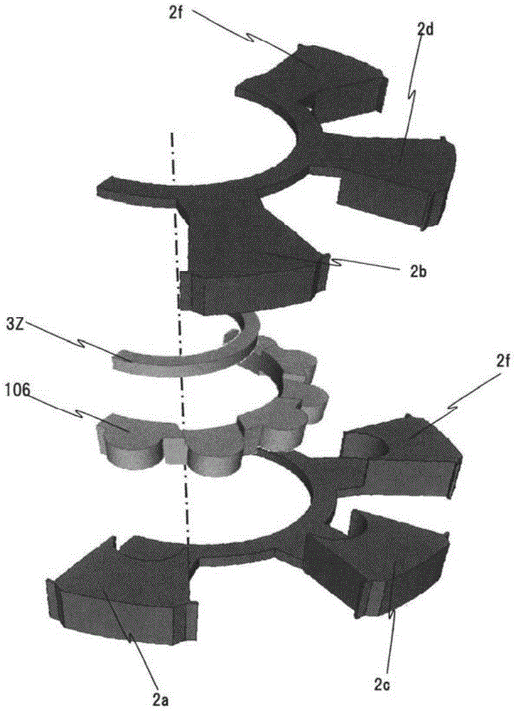
[0060] Below, use Figure 5 A second embodiment of the present invention will be described. Figure 5 It is a figure which three-dimensionally shows the circumferential 1 / 4 part of the stator and the rotor of the permanent magnet type motor which concerns on the 2nd Embodiment of this invention.
[0061] The structure of this embodiment and figure 1 The difference is that the N side protrusions 2a, 2c, 2e, 2g (2c, 2e, 2g not shown) and the S-side protrusions 2b, 2d, 2f, 2h (2d, 2f, 2h not shown) are constituted in a mechanically connected state. In other words, in figure 1 Among them, the N-side convex portion 2a and the S-side convex portion 2b are composed of separate core materials, but in Figure 5 formed into one.
[0062] By adopting such a structure, since the rotor core 2 can be processed integrally, the assembly operation becomes very easy, and the manufacturing cost is significantly reduced accordingly. In addition, since the N-side convex portion and the S-s...
Embodiment 3
[0068] Hereinafter, a third embodiment of the present invention will be described using FIG. 6 . Figure 6A It is a partial sectional view showing the rotor of the permanent magnet motor according to the third embodiment of the present invention in a cross section perpendicular to the rotation axis. Figure 6B It is a partial sectional view showing the rotor of the permanent magnet motor according to the third embodiment of the present invention in a longitudinal section along the rotating shaft. because Figure 6A structure with Figure 3A have the same structure, so their description is omitted.
[0069] Figure 6B structure with Figure 3B The difference in the structure is that a group of components composed of three axial sections A, B, and C are connected in the axial direction. Here, three sets of component structures are shown. Component 1 is structured with Figure 3B The structure is the same, and the cross-sections A, B, and C are formed in order from the pos...
PUM
 Abstract
Description
Claims
Application Information
 - R&D
- Intellectual Property
- Life Sciences
- Materials
- Tech Scout
- Unparalleled Data Quality
- Higher Quality Content
- 60% Fewer Hallucinations
Browse by: Latest US Patents, China's latest patents, Technical Efficacy Thesaurus, Application Domain, Technology Topic, Popular Technical Reports.
© 2025 PatSnap. All rights reserved.Legal|Privacy policy|Modern Slavery Act Transparency Statement|Sitemap|About US| Contact US: help@patsnap.com