Power receiving device, vehicle, and power transmission device

a technology for power transmission devices and receiving devices, which is applied in the direction of charging stations, electric vehicle charging technology, transportation and packaging, etc., can solve the problems of radiated electromagnetic field and leakage to the outside, and achieve the effect of suppressing the leakage of magnetic flux

Active Publication Date: 2018-01-23
TOYOTA JIDOSHA KK +1
View PDF94 Cites 0 Cited by
  • Summary
  • Abstract
  • Description
  • Claims
  • Application Information

AI Technical Summary

Benefits of technology

[0006]In the magnetic shield, magnetic flux emitted from the coil enters the inside of the magnetic sheet, thereby suppressing the leakage of the magnetic flux to the outside. Furthermore, the metal sheet blocks the leakage of the magnetic flux rushing out of the magnetic sheet to the outside.
[0010]By employing this magnetic shield configuration, an eddy current is generated on a surface of a metal sheet by magnetic flux rushing out of the first magnetic sheet. Even in a case where an electromagnetic field is radiated from a surface of the conductive sheet due to this eddy current, the second magnetic sheet can suppress discharge of the electromagnetic field to the outside.

Problems solved by technology

As a result, it is conceivable that this electromagnetic field is radiated from the surface of the metal sheet to the outside, and leaks to the outside.

Method used


Image

  • Power receiving device, vehicle, and power transmission device
  • Power receiving device, vehicle, and power transmission device
  • Power receiving device, vehicle, and power transmission device

Examples


second embodiment

[0059]With reference to FIGS. 10 and 11, a structure of a magnetic shield of this embodiment will be described. FIG. 10 is a diagram as viewed from below showing an arrangement relation between a power receiving unit 210 and a magnetic shield 500A, and FIG. 11 is a sectional view taken along a line XI-XI in FIG. 10.

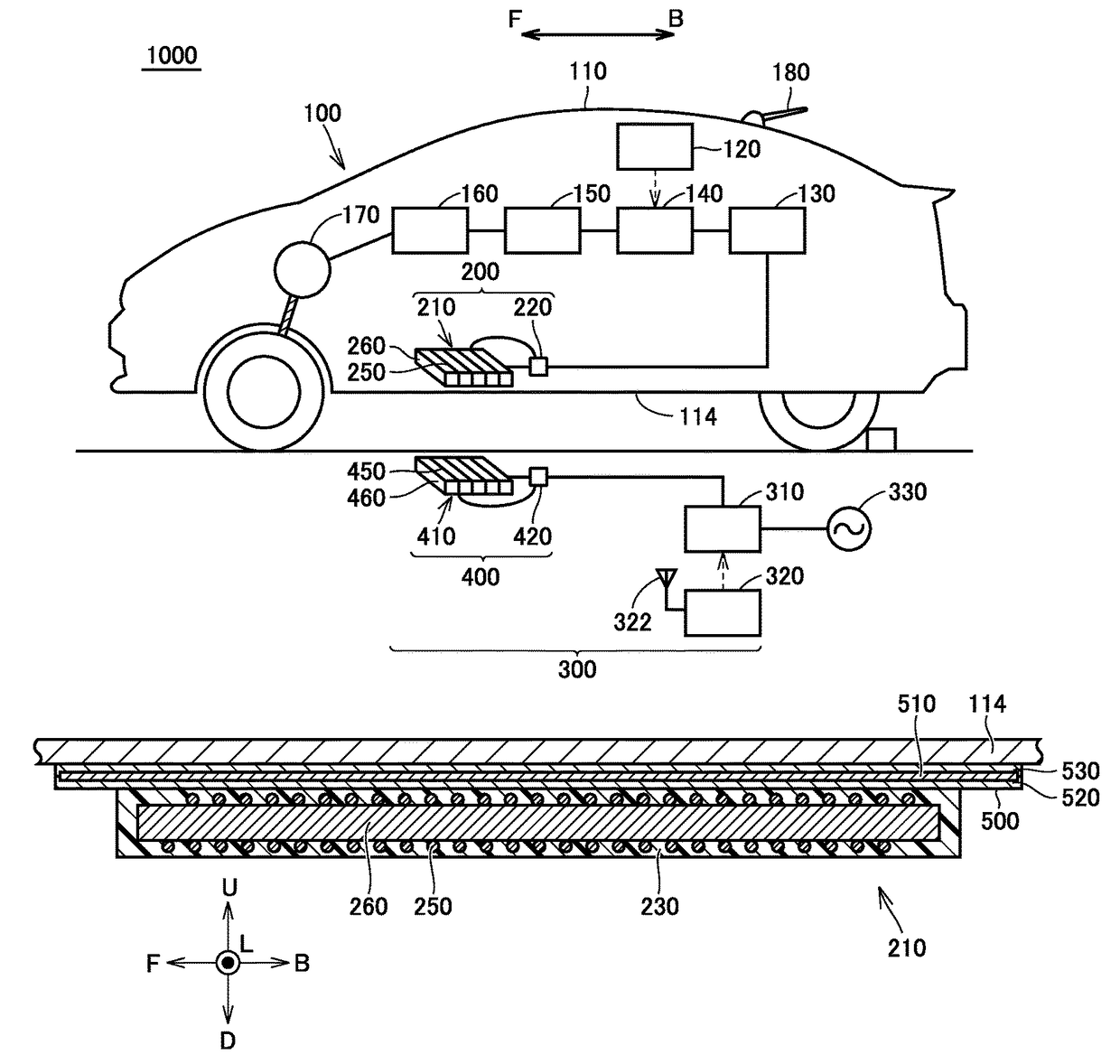
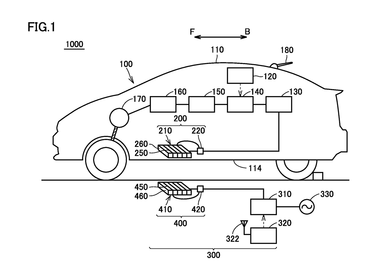
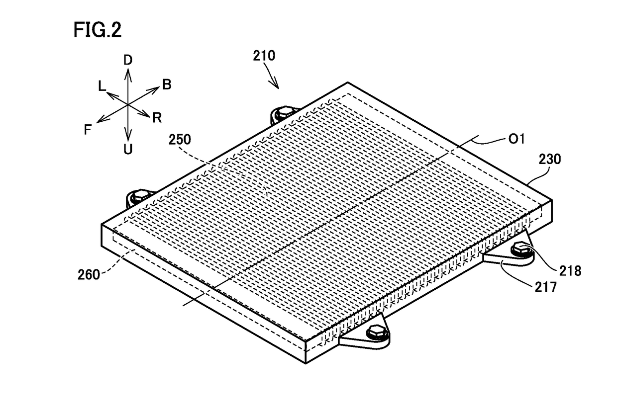
[0060]A metal sheet 510 used in magnetic shield 500 described above has a size including a whole surface of power receiving unit 210 in plan view. However, in a case of using power receiving unit 210 in which a power receiving coil 250 is spirally wound around a core unit 260 of this embodiment with a coil-winding axis (horizontal axis) O1 extending along a front-back direction (arrow BF direction in the drawing) of the above vehicle as the center, magnetic flux is intensively radiated / incident from both ends along coil-winding axis (horizontal axis) O1.

[0061]Accordingly, magnetic shield 500A may be configured such that metal sheet 510 includes two sheets, namely a first ...

third embodiment

[0065]While the attachment of power receiving unit 210 and magnetic shield 500 to floor panel 114 is described in the above embodiment, the attachment of a power transmission unit 410 and a magnetic shield 500 to a parking area B in an external power supply device 300 will be described in this embodiment with reference to FIG. 12 to FIG. 14.

[0066](Structure of Power Transmission Unit 410)

[0067]With reference to FIGS. 12 and 13, a structure of power transmission unit 410 will be described. The basic structure is the same as that of the above power receiving unit 210, and power transmission unit 410 includes a power transmission coil 450, and a core unit 460. In core unit 460, power transmission coil 450 is spirally wound around surroundings including upper and lower surfaces of core unit 460 with a coil-winding axis (horizontal axis) O1 extending along a front-back direction (arrow BF direction in the drawing) of a vehicle as the center. Core unit 460 is the same as core unit 260 of ...

fourth embodiment

[0073]With reference to FIG. 15, a structure of a magnetic shield of this embodiment will be described. Similarly to a case where magnetic shield 500A is partially disposed, as shown in the above second embodiment, magnetic shield 500A may be configured such that a metal sheet 510 includes two sheets, namely a first metal sheet 510A disposed beside a first end along a coil-winding axis (horizontal axis) O1 of a power transmission unit 410, and a second metal sheet 510B disposed beside a second end along coil-winding axis (horizontal axis) O1 of power transmission unit 410.

[0074]In this case, magnetic flux M is emitted (or incident) from each of end faces 461 and 463 of a core unit 460, and therefore first metal sheet 510A is preferably disposed so as to include end face 461 in plan view, and second metal sheet 510B is preferably disposed so as to include end face 463 in plan view. Consequently, it is possible to reduce a cost required for providing the metal sheet, and to reduce wei...


PUM

PropertyMeasurementUnit
thickness t1aaaaaaaaaa
conductiveaaaaaaaaaa
magneticaaaaaaaaaa

Abstract

This power receiving device includes a magnetic shield, and the magnetic shield includes: a first magnetic sheet located beside the power receiving unit; a conductive sheet located opposite to the power receiving unit with the first magnetic sheet interposed therebetween; and a second magnetic sheet located opposite to the first magnetic sheet with the conductive sheet interposed therebetween.

Description

[0001]This nonprovisional application is based on Japanese Patent Application No. 2014-059719 filed on Mar. 24, 2014 with the Japan Patent Office, the entire contents of which are hereby incorporated by reference.BACKGROUND OF THE INVENTION[0002]Field of the Invention[0003]The present invention relates to a power receiving device for receiving power from a power transmission device in a noncontact manner, a vehicle including the power receiving device, and a power transmission device for transmitting power to a power receiving device in a noncontact manner.[0004]Description of the Background Art[0005]As disclosed in Japanese Patent Laying-Open Nos. 2013-154815, 2013-146154, 2013-146148, 2013-110822, and 2013-126327, there have been known power transmission systems using power transmission devices and power receiving devices for transmitting and receiving power in a noncontact manner. WO 2011 / 074091 A and Japanese Patent Laying-Open No. 2013-132171 each disclose a coil and a magnetic...

Claims


Application Information

Patent Timeline
Patent Type & Authority Patents(United States)
IPC IPC(8): H02J5/00H01F38/14B60L11/18H01F27/36
CPCH02J5/005B60L11/182H01F27/367H01F38/14Y02T90/14Y02T10/7005Y02T10/7072Y02T90/122B60L53/12H01F27/36Y02T10/70H01F27/361H02J50/12H02J50/70Y02T90/12
Inventor FUJIMAKI, TAKASHIMORI, AKIRAMATSUZAKI, TORUISHIHARA, TAICHI
Owner TOYOTA JIDOSHA KK
Why Eureka
Try Eureka