Transformer

a transformer and transformer technology, applied in transformers/inductance details, coils, electrical devices, etc., can solve the problems of workability during production and took too much time to wind barrier tape, and achieve the effect of easy connection of primary supporting coils and primary terminals

Active Publication Date: 2014-07-08
TDK CORPARATION
View PDF8 Cites 1 Cited by
  • Summary
  • Abstract
  • Description
  • Claims
  • Application Information

AI Technical Summary

Benefits of technology

[0011]The transformer according to the present invention has a structure wherein a second hollow cylinder part which function as a bobbin main body of the secondary main coil is provided at the outer peripheral side of a first hollow cylinder part which functions as the bobbin main body of the primary main coil, thereby it has a double layer structure wherein the secondary main coil wind around the outer peripheral of the primary main coil. Therefore, the transformer according to the present invention has accomplished to shorten even for a vertical type transformer, and also the present invention can suppress the leakage flux in the vertical direction. Further, the present inventors according to the present invention has found that by having a double layer structure as the present invention, even if the primary supportive coil is provided by shifting in the vertical direction (the first positive direction and the first negative direction) with respect to the secondary main coil, a good connection between the primary supportive coil and the secondary main coil can be achieved. The transformer according to the present invention utilize the advantage of such structure, and by winding the primary supportive coil to other section separated by an intermediate collar part from the section where the secondary main coil is provided, the step for winding the barrier tape around the outer peripheral of the secondary main coil is not needed; thereby the workability during the production is improved. Therefore, the present invention accomplished a good connection between the primary supportive coil and the secondary main coil, can easily ensure the secure insulation between the primary supportive coil and the secondary main coil, has excellent productivity, and can accomplish to make shorter. Also, the transformer according to the present invention can shorten the length of the legs of the core which is inserted to the hollow cylinder part, and enhance the strength of the core.
[0013]By providing the primary terminals of which the both end parts of the primary main coil and primary supportive coil are wound at one end part of the base part, and providing secondary terminals of which the both end parts of the secondary main coil is wound at other end of the base part; a good insulation at the primary side and the secondary side can be ensured. Also, by making the lower collar part shorter than the first end part of the base part, even after the bobbin and the case are assembled, the primary terminal provided at the first end part are prevented from being covered by the case, thereby when the both ends of the primary supportive coil are wound to the first end part or when soldering the primary supportive coil, the case is prevented from intervening, or the case is prevented from being partially damaged.
[0015]As such transformer, the primary supportive coil is closer to lower collar part and the first end part of the base part, therefore the connection of the primary supportive coil and the primary terminals are easy.

Problems solved by technology

In the above described conventional technology, after winding the barrier tape around the outer peripheral of the secondary main coil, in order to wind the primary supportive coil thereover, it took too much time to wind the barrier tape, thus the workability during the production was a problem.

Method used


Image

  • Transformer
  • Transformer
  • Transformer

Examples


Embodiment Construction

[0020]In the following, the present invention is described based on the embodiment shown in the figure.

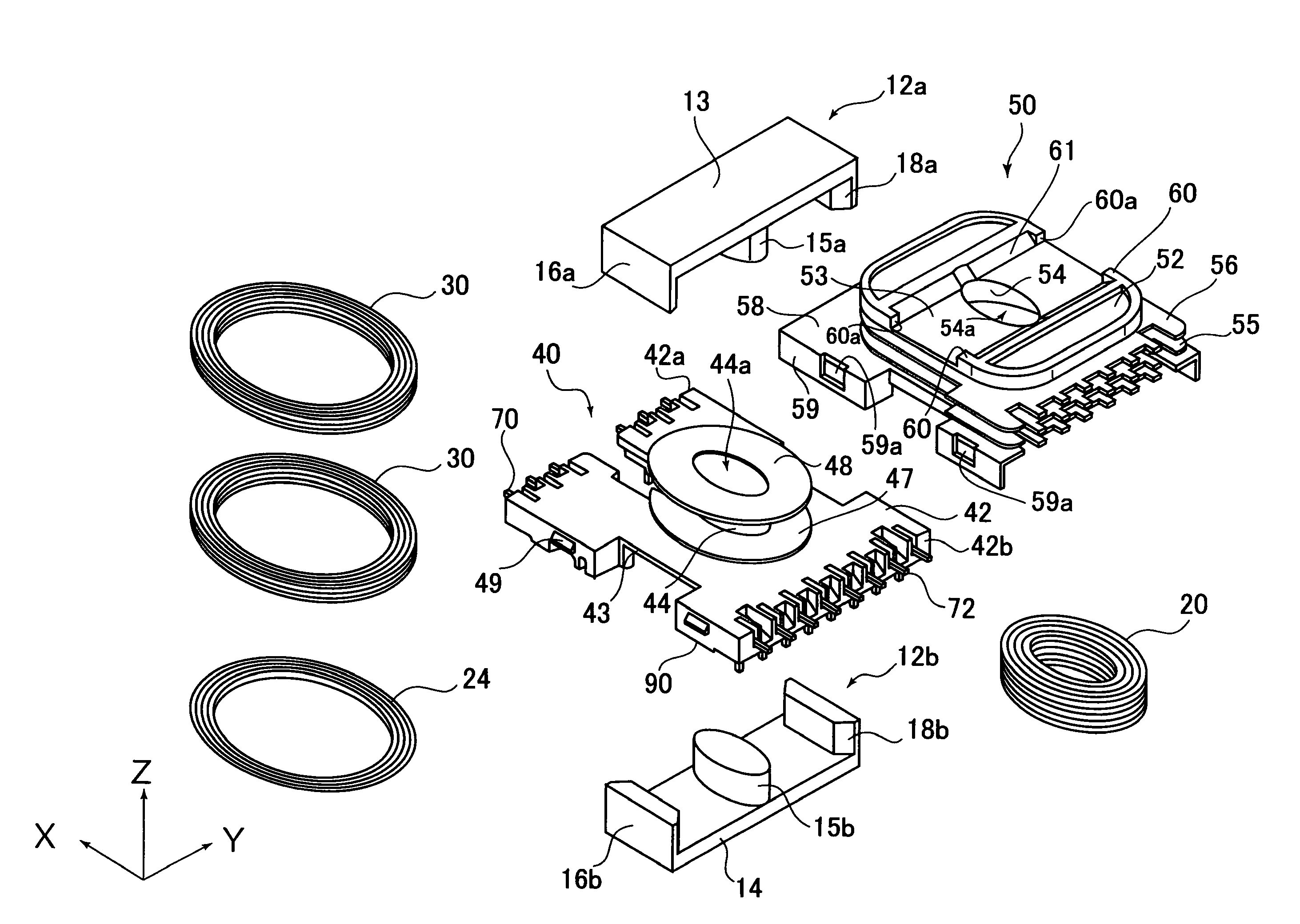
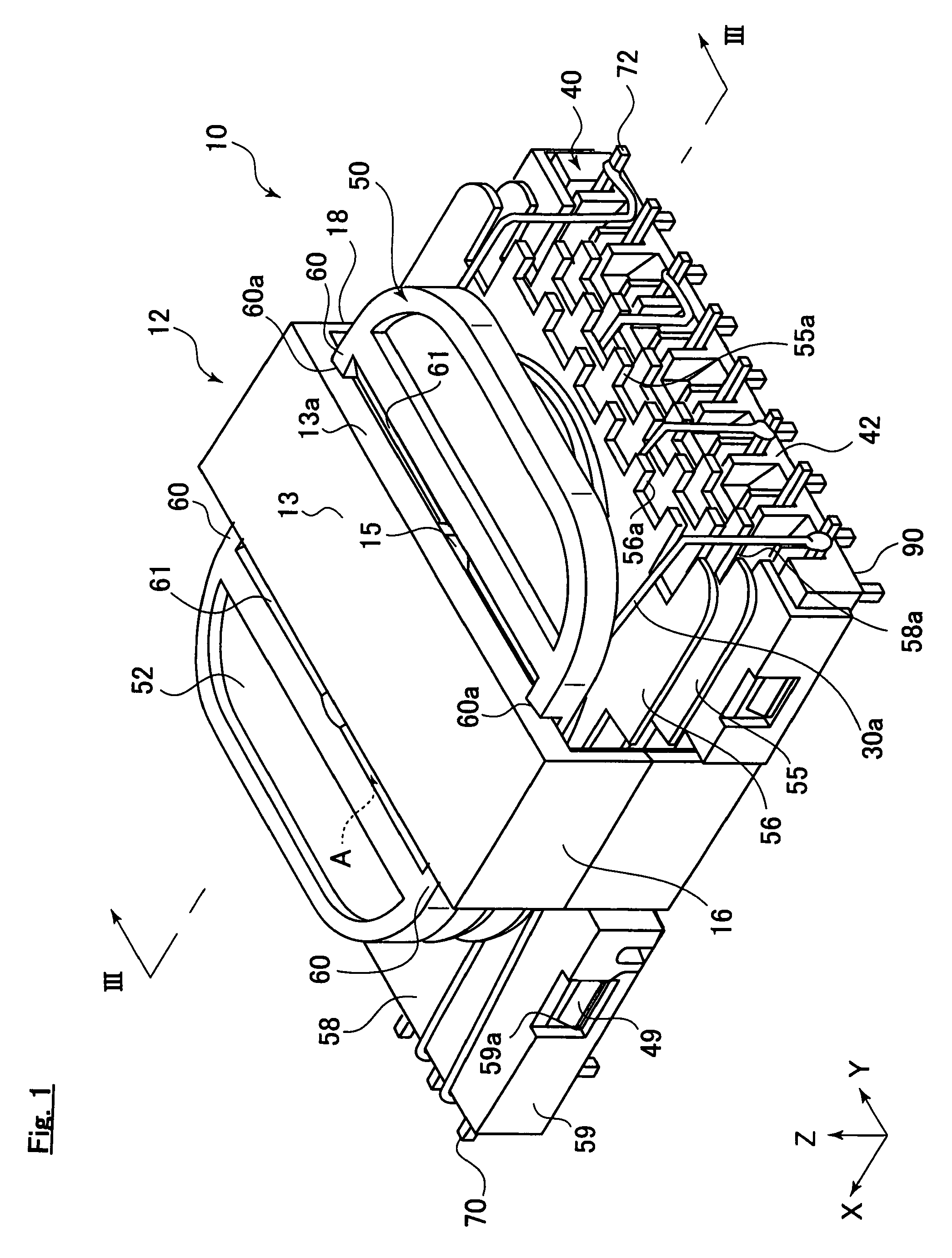
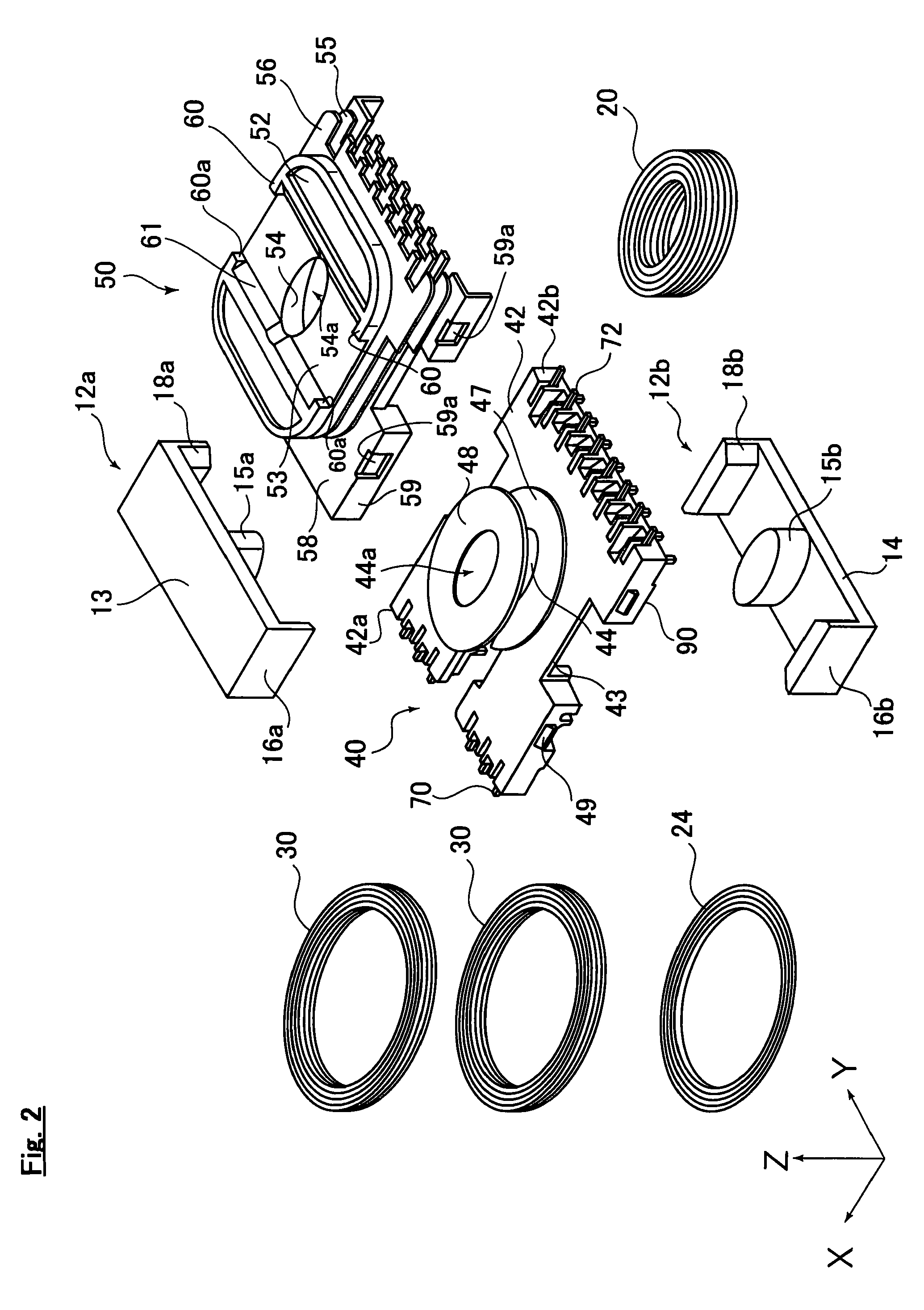
[0021]As shown in FIG. 1, the transformer 10 according to one embodiment of the present invention comprises a core 12, a case 50, and a bobbin 40. Also, as shown in FIG. 3 which is the cross sectional view of FIG. 1, the primary main coil 20, and the primary supportive coil 24 and the secondary main coil 30 are wound around the case 50 and the bobbin 40.

[0022]The core 12 shown in FIG. 1 is constituted by a soft magnetic material such as ferrite or so, and forms flux path allowing the magnetic flux to pass thorough which is generated by the primary main coil 20, the primary supportive coil 24 and the secondary main coil 30 which will be described in below. The core 12 comprises a middle leg 15, side legs 16 and18, a first connection part 13 and a second connection part 14 (refer to FIG. 2). The middle leg 15 of the core 12 extends along the first direction (Z axis direction in the f...


PUM

PropertyMeasurementUnit
workabilityaaaaaaaaaa
lengthaaaaaaaaaa
strengthaaaaaaaaaa

Abstract

A transformer is provided having good workability during production and good connection of the secondary main coil and the primary supportive coil. The transformer has a bobbin with a base part and first hollow cylinder part with a first through hole and a core projecting in a first positive direction from said base part, and a case having an upper collar part formed with a primary main coil wound around said first hollow cylinder part, a second through hole leading to said first through hole, and a second hollow cylinder part formed at the outer peripheral face. Said primary main coil is housed and projects in a first negative direction from said upper collar part. A lower collar part opposes said base part by extending approximately parallel to said mounting face. The primary supportive coil and secondary main coil are wound around said first and second sections, respectively.

Description

BACKGROUND OF THE INVENTION[0001]1. Field of the Invention[0002]The present invention relates to a suitable transformer used together with a power source IC transformer for resonance.[0003]In an electric power source part of an electronic device, there is those including a resonance transformer used together with the power source IC for resonance. As for transformer used as such resonance transformer, the properties corresponding to the function of the power source IC may be demanded. For example, the resonance transformer used together with the power source IC having stand-by (STBY) function may be demanded to improve the connection of the primary supportive coil and the secondary main coil.[0004]As for the resonance transformer which has accomplished a good connection between the primary supportive coil and the secondary main coil, the primary coil is provided at the both sides of the secondary main coil, then the barrier tape is wound around the outer peripheral side of the secon...

Claims


Application Information

Patent Timeline
Patent Type & Authority Patents(United States)
IPC IPC(8): H01F27/30H01F27/28H01F27/29
CPCH01F30/06H01F27/29H01F27/325H01F2005/025
Inventor MAEDA, HIROSHI
Owner TDK CORPARATION
Why Eureka
Try Eureka