Magnetic memory using spin injection flux reversal

a magnetic memory and flux reversal technology, applied in the field of magnetic memory, can solve the problems of insufficient reliability of the aforesaid magnetic memory, and achieve the effect of high reliability and simple manufacturing

Inactive Publication Date: 2010-03-23
TDK CORPARATION
View PDF4 Cites 1 Cited by
  • Summary
  • Abstract
  • Description
  • Claims
  • Application Information

AI Technical Summary

Benefits of technology

[0011]When a current is passed through the write interconnection, magnetic force lines are supplied to the magnetosensing layer via the magnetic yoke. Since the magnetic yoke surrounds the circumference of the write interconnection, it functions to suppress leakage of magnetic flux to adjacent elements and increase the magnetic flux density in the magnetosensing layer. The current flowing into the write interconnection may be smaller than in the case where there is no magnetic yoke. Since a current from the magneto-resistance effect element flows through the read interconnection, this current amount (resistance) depending on the magnetization direction of the magnetosensing layer, stored data can be read through the read interconnection.
[0012]Here, the magnetization direction in the magnetosensing layer is perturbed near the magnetic connection area of the magnetic yoke with the magnetosensing layer. If the magnetization direction of the region of the magnetosensing layer facing the fixed layer which functions during read, is not perturbed, reliability will be higher. Hence, in this magnetometric sensor, the surface area of the fixed layer is made smaller than the surface area of the magnetosensing layer, the magnetization direction in the part of the magnetosensing layer opposite the fixed layer is not perturbed as much as in the surrounding area, and reliability during data read is increased.
[0013]In the magnetic memory according to the present invention, the magnetosensing layer is formed on a substrate, the nonmagnetic layer is formed on the magnetosensing layer, and the fixed layer is formed on the nonmagnetic layer. Since the magnetosensing layer is on the substrate side, the surface area can be increased easily.
[0019]According to this manufacturing method, since the surface area of the fixed layer can be made smaller than the surface area of the magnetosensing layer using the photoresist, a reliable magnetometric sensor can be manufactured easily.
[0023]In this case, the write interconnection is formed easily by lift-off.
[0027]The magnetic memory of the invention is highly reliable, and the method of manufacturing it is simple.

Problems solved by technology

However, the reliability of the aforesaid magnetic memory is not sufficiently high.

Method used


Image

  • Magnetic memory using spin injection flux reversal
  • Magnetic memory using spin injection flux reversal
  • Magnetic memory using spin injection flux reversal

Examples


Embodiment Construction

[0046]Hereafter, referring to the accompanying drawings, some aspects of a magnetic memory according to the invention and the method of manufacturing it will be described in detail. In the description, identical symbols are assigned to identical elements, and their description is not repeated.

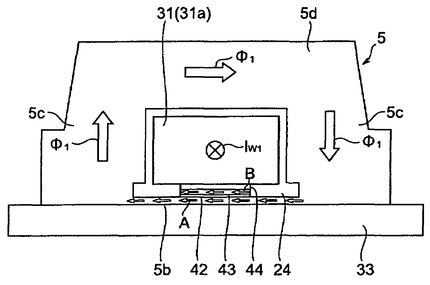
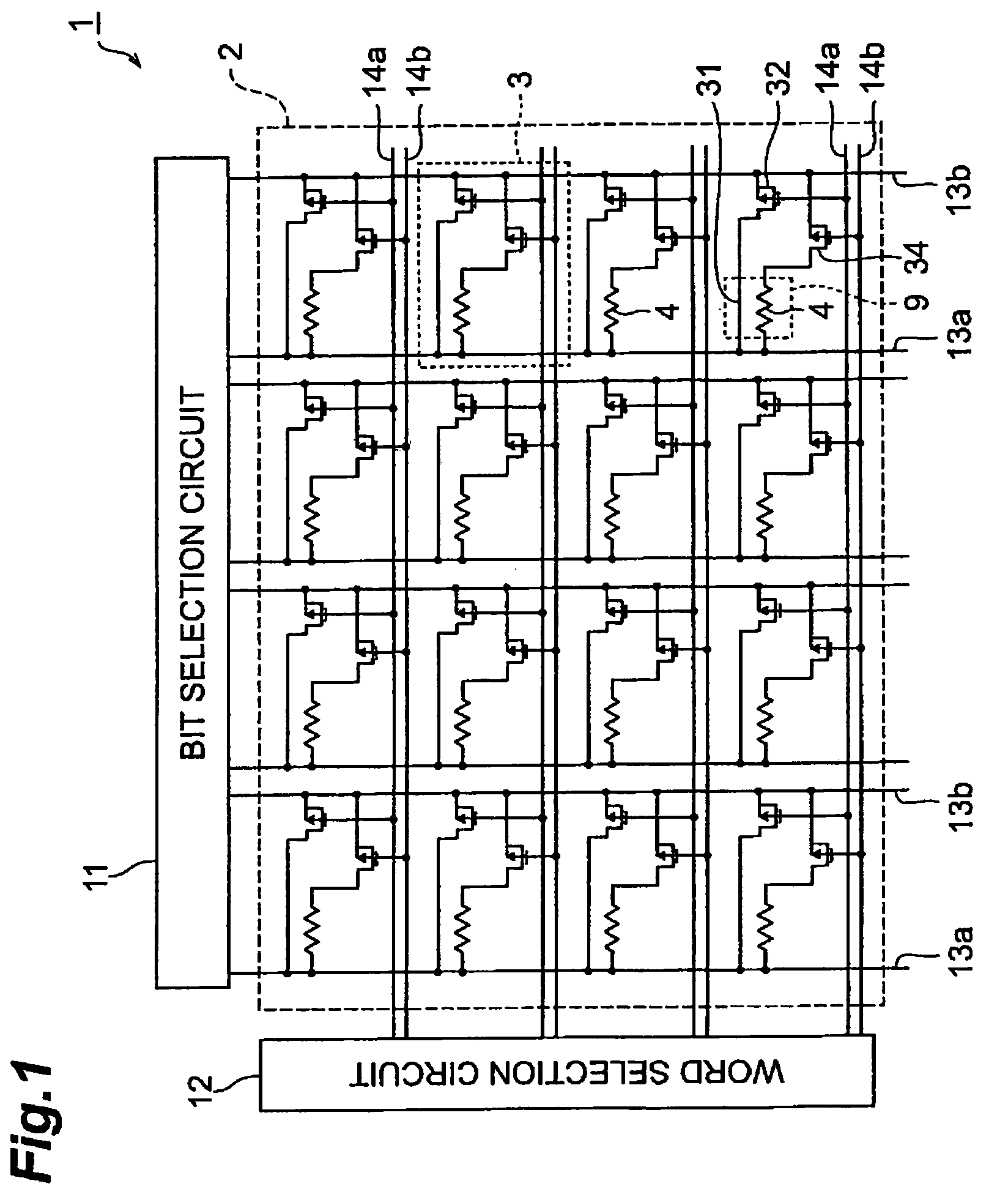
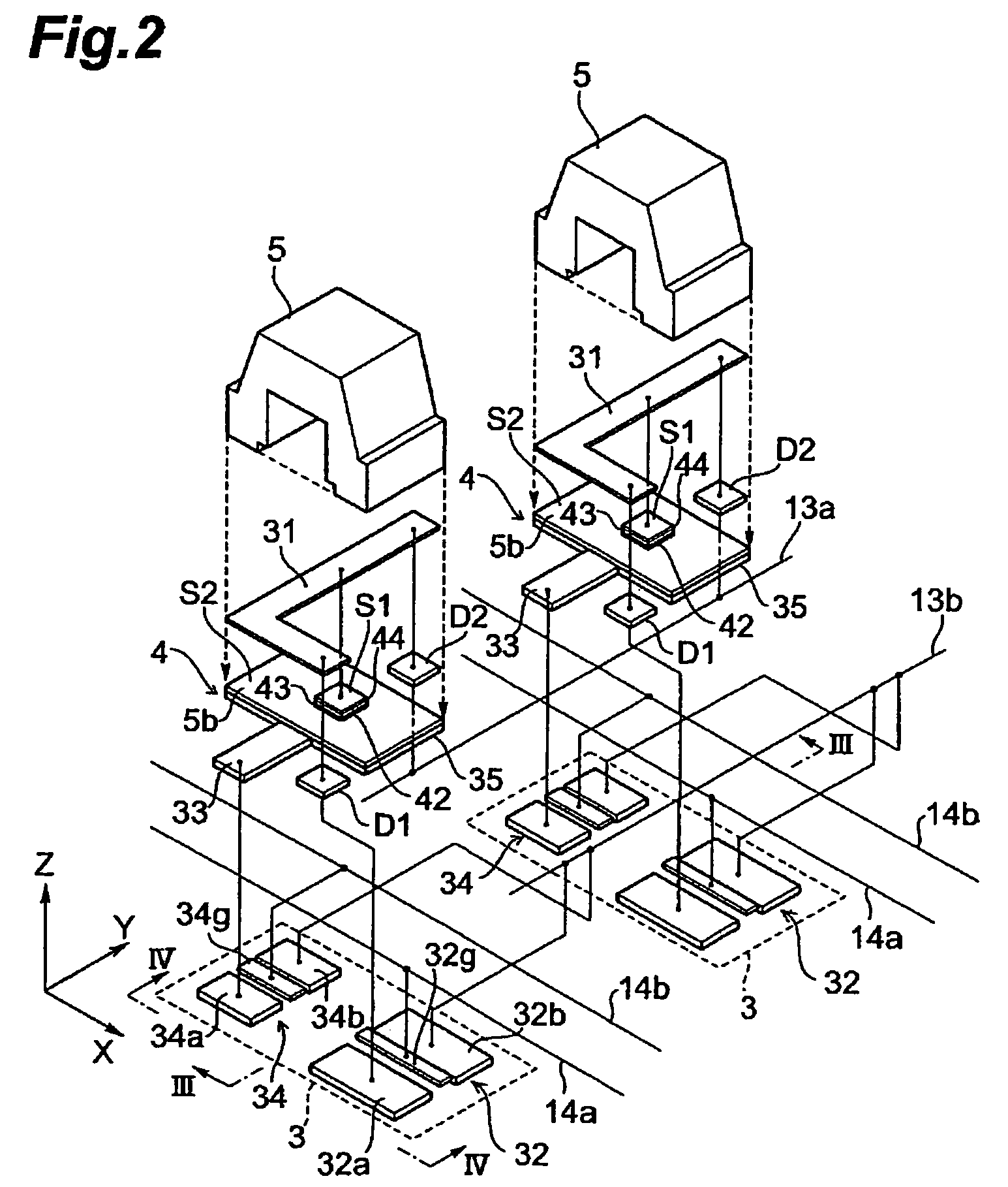
[0047]FIG. 1 is a circuit diagram of a magnetic memory 1 according to this embodiment, and FIG. 2 is a schematic perspective view of a storage area 3 in FIG. 1.

[0048]The magnetic memory 1 comprises a storage part 2, bit selection circuit 11, word selection circuit 12, bit interconnections 13a, 13b and word interconnections 14a, 14b. The storage part 2 comprises plural storage areas 3. The plural storage areas 3 are disposed in a two-dimensional array of m lines and n rows (m and n are integers equal to 2 or more). The plural storage areas 3 each have a magnetic element part 9 comprising a TMR element 4, write interconnection 31, read interconnection 33, write transistor 32 and read transistor 3...


PUM


Abstract

A magnetization direction in a magnetosensing layer (5b) is perturbed near the magnetic connection between a magnetic yoke (5) and the magnetosensing layer (5b). If the magnetization direction of a region in the magnetosensing layer (5b) facing a fixed layer which functions during read is not perturbed, reliability is improved. In this magnetometric sensor, a surface area S1 of fixed layers (43, 44) is made smaller than a surface area S2 of the magnetosensing layer (5b) so that, in the region of the magnetosensing layer (5b) facing the fixed layer, the magnetization direction is perturbed less than in the surrounding region and reliability during data read is improved.

Description

BACKGROUND OF THE INVENTION[0001]1. Field of the Invention[0002]The present invention relates to a magnetic memory and to a method of manufacturing same.[0003]2. Related Background Art[0004]In recent years, MRAM (Magnetic Random Access Memory) is attracting attention as a memory device for information processors such as computers and telecommunications devices. Since MRAM stores data by magnetism, it has the advantage that it does not suffer from the inconveniences associated with a volatile memory such as DRAM (Dynamic Random Access Memory) or SRAM (Static RAM), where information would be lost if for example the power supply were interrupted.[0005]MRAM is dramatically superior as regards access speed, reliability and poser consumption compared to a nonvolatile storage means like a conventional flash EEPROM or a hard disk drive. Therefore, MRAM has the potential to assume all the functions of volatile memories such as DRAM and SRAM, and the functions of nonvolatile storage means suc...

Claims


Application Information

Patent Timeline
Patent Type & Authority Patents(United States)
IPC IPC(8): H01L29/82G11C11/02
CPCB82Y10/00H01L27/228H01L43/12H10B61/22H10N50/01
Inventor KOGA, KEIJI
Owner TDK CORPARATION
Why Eureka
Try Eureka