
Motor controller

A control device and motor technology, applied in the direction of single motor speed/torque control, torque pulsation control, measuring device, etc., can solve the problems that digital operations cannot follow the speed, complicated circuit structure, etc., and achieve high-precision control and circuit structure simple effect

Active Publication Date: 2015-03-18
ALPS ALPINE CO LTD
View PDF6 Cites 3 Cited by
  • Summary
  • Abstract
  • Description
  • Claims
  • Application Information

AI Technical Summary

Problems solved by technology

[0005] The motor control device described in Patent Document 1 generates a drive signal for driving a three-phase motor through digital calculation, so the circuit structure is complicated
Furthermore, since digital calculations take time, if the motor is to be rotated at high speed, the problem that digital calculations cannot follow the rotational speed arises.

Method used


Image

  • Motor controller
  • Motor controller
  • Motor controller

Examples


Embodiment Construction

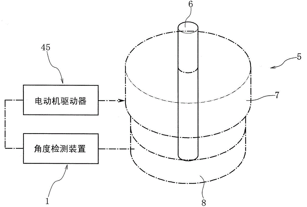
[0063] figure 1 The illustrated motor control device 5 has a rotation shaft 6 , a rotation drive unit 7 that drives the rotation shaft 6 , and a rotation detection unit 8 that detects the rotation of the rotation shaft 6 .

[0064] Such as Figure 8 As shown, the rotation drive unit 7 constitutes a drive unit of the brushless motor, and has a rotor magnet 41 that rotates together with the rotation shaft 6 . Inside the rotor magnet 41 , three-phase stator yokes 42 are arranged at an angle of 120 degrees with respect to the rotation direction, and U-phase, V-phase, and W-phase motor coils 43 are connected to each stator yoke 42 .

[0065] The rotation detection unit 8 constitutes a part of the angle detection device 1 . The motor driver 45 is controlled by the angle detection output obtained by the angle detection device 1 , and three-phase drive power is applied from the motor driver 45 to the motor coil 43 .

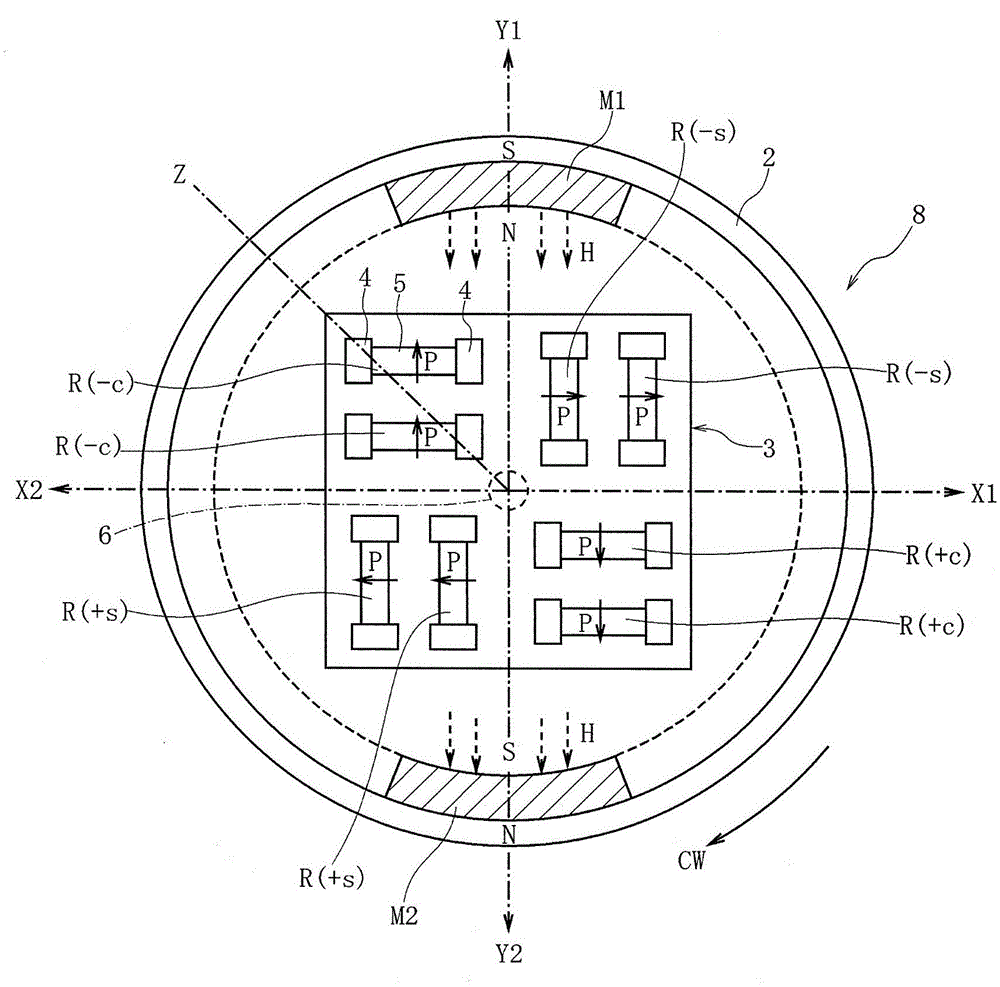
[0066] Such as figure 2As shown, a rotation body 2 that rotate...


PUM


Abstract

The outputs from a first magnetic detector (11) and a second magnetic detector (12) are supplied to first to fourth output circuits (21, 22, 23, and 24) which are differential amplifiers, whereby detected outputs (S1 and S2) which are analogous to a sine wave and whose positive-negative polarities are opposite to each other, and detected outputs (S3 and S4) which are analogous to a cosine wave and whose positive-negative polarities are opposite to each other are obtained. The detected outputs (S1 to S4) are supplied to a switching circuit (31), and detected output portions are obtained at intervals of 90° from the detected outputs (S1 to S4). A bias adding circuit 33 applies a bias voltage to each of the detected output portions to obtain an angle detection output analogous to a linear function. The angle detection output is used to determine the supply timing at which a three-phase driving current is supplied.

Description

technical field [0001] The present invention relates to a motor control device that controls three-phase drive power using an analog output that approximates a linear function proportional to the rotation angle of a rotary shaft. Background technique [0002] In a motor control device that controls a three-phase motor, drive power of three phases, U-phase, V-phase, and W-phase, is applied to the motor coils in accordance with the rotation phase of the motor. [0003] In the motor control device described in Patent Document 1 below, a motor control signal is calculated in a calculation processing unit, and a drive signal for each phase of a three-phase motor is calculated by a logic circuit provided with the motor control signal. Based on the drive signal, the pre-drive circuit is controlled to control the drive of the three-phase motor. [0004] [Patent Document 1] WO2012 / 102113 A1 [0005] The motor control device described in Patent Document 1 generates a drive signal fo...

Claims


Application Information

Patent Timeline
Patent Type & Authority Applications(China)
IPC IPC(8): H02P6/10H02P6/16G01D5/245H02P6/06H02P6/08
CPCH02P6/16H02P6/12H02P6/10G01R33/09
Inventor 中村德男
Owner ALPS ALPINE CO LTD
Learn More