Hair-removing device

A hair remover, hair technology, applied in the field of hair remover, to achieve the effect of good skin contact effect

Active Publication Date: 2008-11-12
BRAUN AG
View PDF11 Cites 2 Cited by
  • Summary
  • Abstract
  • Description
  • Claims
  • Application Information

AI Technical Summary

Problems solved by technology

The limitation is also that the drive pin can only drive the

Method used


Image

  • Hair-removing device
  • Hair-removing device
  • Hair-removing device

Examples


Embodiment Construction

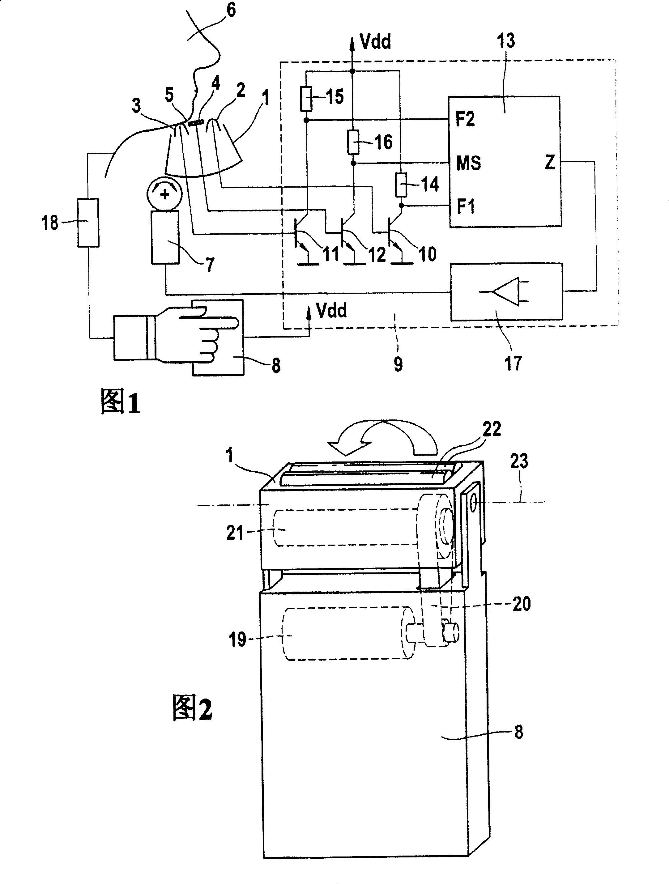
[0033] Fig. 1 is a functional diagram showing an embodiment of an electric shaver designed according to the present invention. The figure relates to a situation during hair removal. It not only presents the functional elements of the shaver highly schematically, but also gives a possible wiring of the electronic elements for carrying out the positioning method according to the invention. In the embodiment concerning the razor, the razor has a rotatable head 1 mounted for rotation about an axis perpendicular to the plane of the drawing. The cutter head 1 includes a first blade 2 , a second blade 3 and a center cutter 4 installed between the blades 2 and 3 . In the illustrated situation, the second blade 3 is in physical contact with the skin surface 5 of the user 6 . The cutter head 1 is rotated relative to the housing 8 in the hand of the user 6 via the positioning device 7 . The two blades 2 and 3 and the center cutter 4 are electrically connected to the circuit 9 respecti...


PUM


Abstract

The invention relates to a hair-removing device comprising a movable actuator head (1) and/or at least one movable actuator support (25, 28), which is/are provided with at least one actuator element (22, 27) for removing hair on a skin surface (5). The invention is characterized by the fact that said hair-removing device further comprises a device for detecting a parameter that relates to the position of the actuator element (22, 27) relative to the skin surface (5), at least one actively actuated positioning device (7) for modifying the position of the actuator head (1) and/or the actuator support (25, 28), and a control device for triggering the positioning device (7) according to the detected parameter.

Description

technical field [0001] The invention relates to a hair remover with a movable actuator head and / or at least one movable actuator carrier. The invention also relates to a method of positioning at least one actuator element on a hair remover. Background technique [0002] The movable actuator head is used as a rotatable cutter head in an electric razor. The mobility of the cutter head is to better adhere to the skin surface during shaving, so as to produce the most ideal shaving effect. [0003] For example, DE3610736A1 discloses an electric razor with a cutter head system. The cutter head system is rotatably mounted relative to the razor housing. It is driven by an electric motor installed in the casing, and is driven by a driving pin to generate an oscillating motion. During the shaving process, the cutter head system is moved passively in rotation, ie the cutter head system is pressed against the skin surface in a rotational position which is predetermined by the actual...

Claims


Application Information

Patent Timeline
IPC IPC(8): B26B19/00A45D26/00B26B19/04B26B19/10B26B19/38
CPCB26B19/10B26B19/04B26B19/388A45D26/0028B26B19/38B26B19/063B26B19/386
Inventor 伯恩哈德·克劳斯亚历山大·克洛斯
Owner BRAUN AG
Why Eureka
Try Eureka