
Eureka
For R&D, Eureka makes reading and utilizing patents & technical documents easy.
Eureka AIR
Designed for self-driven R&D workflows. Generate viable solutions, solve complex R&D challenges, empower your innovation with AI.

Eureka Materials
Designed for material experts only. Revolutionize your material R&D, from search, analyze, to developing new materials.

TechResearch
Generate reliable direction feasibility study reports for your R&D in just a few steps.

TechSeek
Discover and master advanced knowledge NOW. Basics, ideas, possibilities, all at once.

TechMind
As an expert in R&D Theories, TechMind can generates customized viable solutions instantly.

TechRisk
Analyze your overall solution with one click, know your potential R&D risks in advance.

TechMonitor
Get weekly tech updates, stay abreast of the latest tech innovations and key insights.
Dc Restoration For Synchronization Signals
A technique for synchronizing signals and restoring circuits, which is applied in the field of DC components and can solve problems such as receiving side errors and capability impacts
- Summary
- Abstract
- Description
- Claims
- Application Information
AI Technical Summary
Problems solved by technology
Method used
Image

Examples
Embodiment Construction
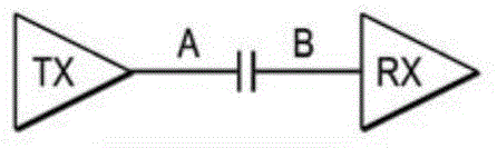
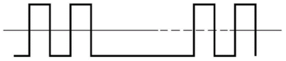
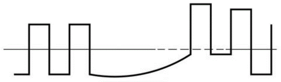
[0019] figure 1 A schematic diagram of an exemplary system with alternating current (AC) coupled links is shown. The system includes a transmit circuit (denoted "TX") configured to transmit a synchronization signal (denoted as a capacitor in the link to provide capacitive coupling) to a receive circuit (denoted "RX") over an AC-coupled link. The synchronization signal is used to trigger functions in the receiving circuit. For example, the synchronization signal may have one or more timing pulses, and the receiving circuitry may be triggered by or operate in response to a threshold crossing of the synchronization signal (ie, the synchronization signal changes polarity between a "high" and a "low" state). The proper operation of the system depends heavily on the integrity of the synchronization signals. The correct synchronization signal ensures that the function in the receiving circuit will be triggered when required, and when the function is triggered, the function is trigg...
PUM
 Abstract
Description
Claims
Application Information
 - R&D Engineer
- R&D Manager
- IP Professional
- Industry Leading Data Capabilities
- Powerful AI technology
- Patent DNA Extraction
Browse by: Latest US Patents, China's latest patents, Technical Efficacy Thesaurus, Application Domain, Technology Topic, Popular Technical Reports.
© 2024 PatSnap. All rights reserved.Legal|Privacy policy|Modern Slavery Act Transparency Statement|Sitemap|About US| Contact US: help@patsnap.com