Magnetic shielding apparatus and magnetic shielding method

A technology of magnetic shielding and shielding cover, applied in shielding devices, magnetic/electric field shielding, measuring devices, etc., can solve the problems of not considering the magnetization component of the magnetic shielding cover and the magnetic field gradient created by the magnetic shielding cover

Inactive Publication Date: 2015-03-18
SEIKO EPSON CORP
View PDF13 Cites 13 Cited by
  • Summary
  • Abstract
  • Description
  • Claims
  • Application Information

AI Technical Summary

Problems solved by technology

[0009] However, in the techniques described in Patent Documents 1 to 8, there is a problem that it is difficult to create an environment where the magnetic field gradient is extremely weak inside the magnetic shield.
Specifically, in the prior art, although the magnetic field from the outside can be reduced, the magnetization components etc. of the magnetic shield are not taken into consideration, so there is a problem that a gradient occurs in the magnetic field state inside the magnetic shield.

Method used


Image

  • Magnetic shielding apparatus and magnetic shielding method
  • Magnetic shielding apparatus and magnetic shielding method
  • Magnetic shielding apparatus and magnetic shielding method

Examples


Embodiment approach

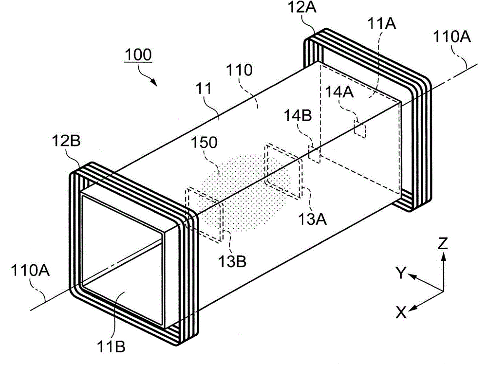
[0055] figure 1 It is an overview perspective view of the magnetic shielding device 100 according to this embodiment. The magnetic shielding device 100 is used to shield the magnetic measurement device to block external magnetic fields such as geomagnetism when measuring a weak current from a living body as a magnetic force, for example.

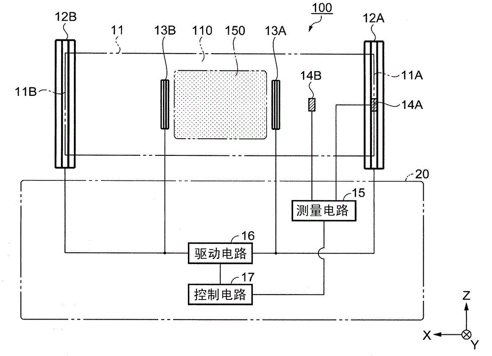
[0056] The magnetic shielding device 100 has: a passive shield 11, external coils 12A, 12B that correct the internal magnetic field of the passive shield 11, a first magnetic sensor 14A, a second magnetic sensor 14B, and a passive shield 11 Internal coils 13A, 13B, and control unit 20 (refer to figure 2 ). Here, the external coils 12A and 12B are an example of the "first coil" according to the invention, and the internal coils 13A and 13B are an example of the "second coil" according to the invention.

[0057] The passive shield cover 11 has a cylindrical shape in which the inside is a cavity, and the axial direction thereof is arranged on a pe...

Deformed example 1

[0143] Configuration example of magnetic sensor

[0144] The configuration of the first magnetic sensor 14A etc. for measuring the magnetic field strength is not limited to figure 2 The configuration shown. Several configurations of the first magnetic sensor 14A and the like will be described below.

[0145] Image 6 It is an overview diagram showing the magnetic shielding device 200 of the second arrangement example. In this example, only one external coil 12A is driven and the other external coil 12B is not driven. Therefore, the control of the inflow magnetic field gradient executed by the control circuit 17 can be simplified.

[0146] Figure 7 It is an overview diagram showing the magnetic shielding device 300 of the third arrangement example. In this example, two sets of magnetic sensors are provided: a magnetic sensor that measures the inflow magnetic field flowing into the passive shield 11 and a magnetic sensor that measures the magnetic field of the internal space 110. ...

Deformed example 2

[0153] The cross-sectional shape of the passive shield cover 11 in the X direction is not limited to the shape described in the foregoing embodiment. For example, it may be a polygonal shape or a circular shape, or a shape obtained by combining a straight line and a curved line on the outer periphery. Specifically, the cross-sectional shape of the passive shield cover 11 can be a quadrilateral, a pentagon, a hexagon, a heptagon, an octagon, or the like if it is a polygon in addition to a circle or an ellipse.

[0154] In addition, the passive shield cover 11 does not need to have the openings 11A, 11B, or may be provided with only one of the openings 11A, 11B. Alternatively, the openings 11A and 11B may be covered with a cover or the like. The shape of the passive shielding cover 11 has a degree of freedom, so that the magnetic shielding device 100 can be applied to various magnetic measuring devices.


PUM


Abstract

A magnetic shielding apparatus includes: a passive shield; a correction target space that is defined in the interior of the passive shield; external coils as a first coil that corrects a magnetic field in the passive shield; a first magnetic sensor; a second magnetic sensor that is arranged more inside the passive shield than the first magnetic sensor; and a control unit. The first magnetic sensor and the second magnetic sensor measure a magnetic field gradient in the passive shield. The control unit controls the external coils based on a result of the measurement performed by the first magnetic sensor and the second magnetic sensor.

Description

Technical field [0001] The invention relates to a magnetic shielding device and a magnetic shielding method. Background technique [0002] Image diagnosis is widely used in the medical field. Since image diagnosis is non-invasive, it places less burden on the human body, and is particularly preferred when examining internal organs such as the heart and brain that are important for life activities. [0003] The internal organs of a living body always generate a weak current due to the activity of neurons. By measuring the magnetic field generated by the current, the state of the internal organs can be understood. [0004] Specifically, the magnetic field caused by living organisms is extremely weak, being 0.1 pico Tesla (1×10 -13 T) to 10 pico Tesla (1×10 -11 T) Degree. [0005] One of the methods to detect and visualize this magnetic field is to draw a magnetic field source. For example, a method of recording a magnetic field formed by the activity of the heart is known as a magneto...

Claims


Application Information

Patent Timeline
Patent Type & Authority Applications(China)
IPC IPC(8): H05K9/00G01R33/022
CPCG01R1/18G01R33/0076G01R33/025H05K9/0071
Inventor 保刈龙治
Owner SEIKO EPSON CORP
Why Eureka
Try Eureka