Unlock instant, AI-driven research and patent intelligence for your innovation.

Common Rail Reagent Injection System

A technology of injection system and common rail pipe, applied in the field of reagent injection system

Active Publication Date: 2017-08-08
TENNECO AUTOMOTIVE OPERATING CO INC
View PDF7 Cites 0 Cited by
  • Summary
  • Abstract
  • Description
  • Claims
  • Application Information

AI Technical Summary

Problems solved by technology

Therefore, such large-scale applications may be difficult to design to overcome various issues such as maintaining proper injector pressure, system robustness, adequately reducing harmful emissions (e.g., particulate matter and NO x ), cost and maintenance etc.

Method used


Image

  • Common Rail Reagent Injection System
  • Common Rail Reagent Injection System
  • Common Rail Reagent Injection System

Examples


Embodiment Construction

[0015] Embodiments of the present invention will be described in detail below in conjunction with the accompanying drawings.

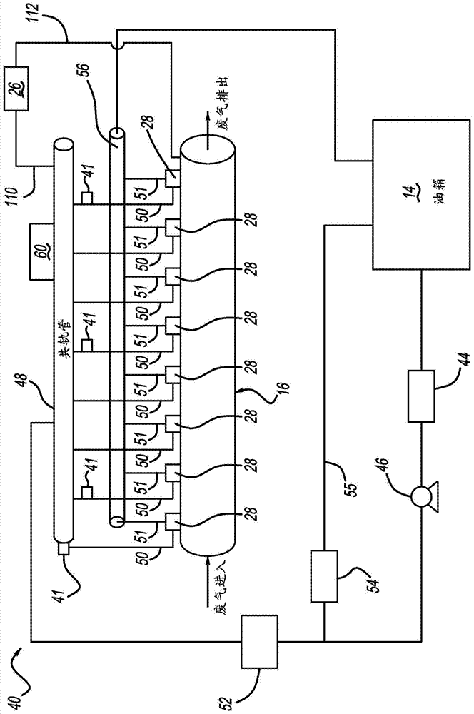
[0016] figure 1 An exhaust system 10 according to the invention is shown schematically. Exhaust system 10 includes at least one engine 12 in communication with a fuel source 14 that, upon consumption, produces exhaust that is expelled into an exhaust passage 16 having an exhaust aftertreatment system 18 . Downstream of the engine 12 may be a DOC assembly 20 , a DPF assembly 22 , and an SCR assembly 24 . Although not required in the present invention, the exhaust aftertreatment system 18 may further include components such as a burner 26 to increase the temperature of the exhaust passing through the exhaust passage 16 . In cold conditions and when engine 12 is started, increasing the temperature of the exhaust gas facilitates ignition of the catalysts in DOC assembly 20 and SCR assembly 24 and, if desired, regeneration initiation of DPF 22 . To provi...


PUM


Abstract

An exhaust system includes a selective catalytic reduction (SCR) assembly and an oxidation catalyst assembly. The exhaust system also includes an exhaust fluid injection system for dispersing exhaust fluid into the exhaust flow at a location adjacent to the SCR assembly or the oxidation catalyst assembly, wherein the exhaust fluid injection means includes a common rail that pressurizes The exhaust treatment fluid is provided to a plurality of injectors that dose the exhaust treatment fluid into the exhaust flow. The exhaust fluid injection device also includes a return rail for returning unused exhaust fluid to the fluid source.

Description

technical field [0001] The invention relates to a reagent injection system for an exhaust system. Background technique [0002] This section provides background information that is not necessarily prior art that is not necessarily prior art to the present invention. [0003] Emissions regulations mandate that engines should have exhaust aftertreatment systems to eliminate, or at least substantially minimize, e.g. particulate matter, NO x etc. emissions. To eliminate and reduce particulate matter and NO x For emissions, the exhaust aftertreatment system may include components such as particulate filters (eg, diesel particulate filter (DPF)), selective catalytic reduction (SCR) components, and diesel oxidation catalyst (DOC) components. [0004] SCR and DOC components generally work in conjunction with a reagent injection system that injects reagent into the exhaust gas stream to treat the exhaust before it enters the SCR and DOC components. For SCRs, a reagent solution in...

Claims


Application Information

Patent Timeline
Patent Type & Authority Patents(China)
IPC IPC(8): F01N3/10F01N3/20B01D53/94
CPCB01D53/90B01D53/9477B01D2251/2067B01D2251/208F01N3/025F01N3/035F01N3/103F01N3/2066F01N2610/02F01N2610/03F01N2610/14F01N2610/1406F01N2610/1433Y02T10/12B01D53/94F01N3/021F01N3/10F01N3/208
Inventor 迈克尔·戈林蒂姆·加德纳郑贯宇倪志
Owner TENNECO AUTOMOTIVE OPERATING CO INC