Insect trap device
A technology for traps and insects, applied in the field of insect traps, can solve the problems of high price, complex production process of insect trapping devices, restrictions on popularization, etc., and achieve the effects of prolonging residence time, increasing volatilization, and improving capture efficiency.
- Summary
- Abstract
- Description
- Claims
- Application Information
AI Technical Summary
Problems solved by technology
Method used
Image

Examples
no. 1 example
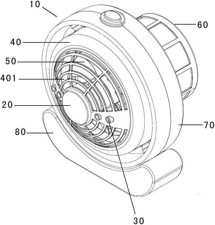
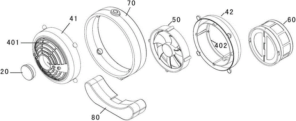
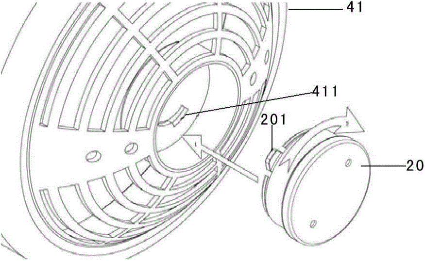
[0033] figure 1 is a schematic diagram showing the overall structure of the insect trap 10 according to the first embodiment of the present invention. figure 2 is a schematic diagram showing an exploded structure of the insect trap 10 according to the first embodiment of the present invention. like figure 1 and figure 2 As shown, the insect trap 10 includes a bait box 20 , a lighting device 30 , a housing 40 , a fan device 50 and a collecting device 60 . The bait box 20 is used to place bait and attract mosquitoes by emitting bait volatiles, and the light emitting device 30 attracts mosquitoes by emitting light. The housing 40 is formed as a hollow cylinder whose cross section is substantially circular. The housing 40 includes an air inlet 401 provided at one end thereof (the end is hereinafter referred to as "an air inlet end") and an air outlet 402 provided at the other end, and the air inlet 401 and The exhaust port 402 communicates with the hollow portion of the bar...
no. 2 example
[0050] Figure 7 A second embodiment of an insect trap according to the invention is shown. The difference between the second embodiment and the first embodiment mainly lies in: the position of the air inlet and the position of the bait box. like Figure 7 As shown, the insect trap according to the second embodiment has a vertical layout, wherein the casing 400 is formed as a hollow cylinder, and the fan device 500 is disposed in the hollow portion of the cylinder. The casing 400 has an air inlet at one end (hereinafter referred to as "an air inlet end") and an air outlet at the other end. The housing 400 is supported with an end cover 900 by a plurality of pillars 800 at the end of the air inlet, so that the gap between the plurality of pillars 800 is formed as an air inlet. The light emitting device 300 is suspended below the end cover 900 .
[0051] exist Figure 7 In Figures A-D, various possible arrangements of the bait box 200 are shown. For example, if Figure 7 ...
PUM
 Abstract
Description
Claims
Application Information
 - R&D
- Intellectual Property
- Life Sciences
- Materials
- Tech Scout
- Unparalleled Data Quality
- Higher Quality Content
- 60% Fewer Hallucinations
Browse by: Latest US Patents, China's latest patents, Technical Efficacy Thesaurus, Application Domain, Technology Topic, Popular Technical Reports.
© 2025 PatSnap. All rights reserved.Legal|Privacy policy|Modern Slavery Act Transparency Statement|Sitemap|About US| Contact US: help@patsnap.com