A double hook stirrup automatic forming machine

An automatic forming machine and stirrup technology, which is applied in the field of construction machinery and equipment, can solve the problems of complex processing procedures, time-consuming, labor-intensive, and time-wasting problems, and achieve the effects of high automation, reduced safety hazards, and reduced workload

Active Publication Date: 2016-11-09
RUZHOU ZHENGTIE SANJIA CEMENT PROD
View PDF5 Cites 0 Cited by
  • Summary
  • Abstract
  • Description
  • Claims
  • Application Information

AI Technical Summary

Problems solved by technology

With the development of technology, the bending process has been widely used in stirrup machines for processing, but most stirrup machines need to Manual transfer assistance for multiple processes
In addition, during the bending process of steel bars, parts that do not need to be stamped will often be distorted and deformed due to the stamping force, resulting in complicated subsequent processing procedures.
Sometimes it is necessary to manually straighten the middle part of the steel bar by manual beating. These methods are not only time-consuming, laborious, time-consuming, but also have great potential safety hazards and increase costs.

Method used


Image

  • A double hook stirrup automatic forming machine
  • A double hook stirrup automatic forming machine
  • A double hook stirrup automatic forming machine

Examples


Embodiment Construction

[0028] Below in conjunction with accompanying drawing and embodiment the present invention is described in further detail:

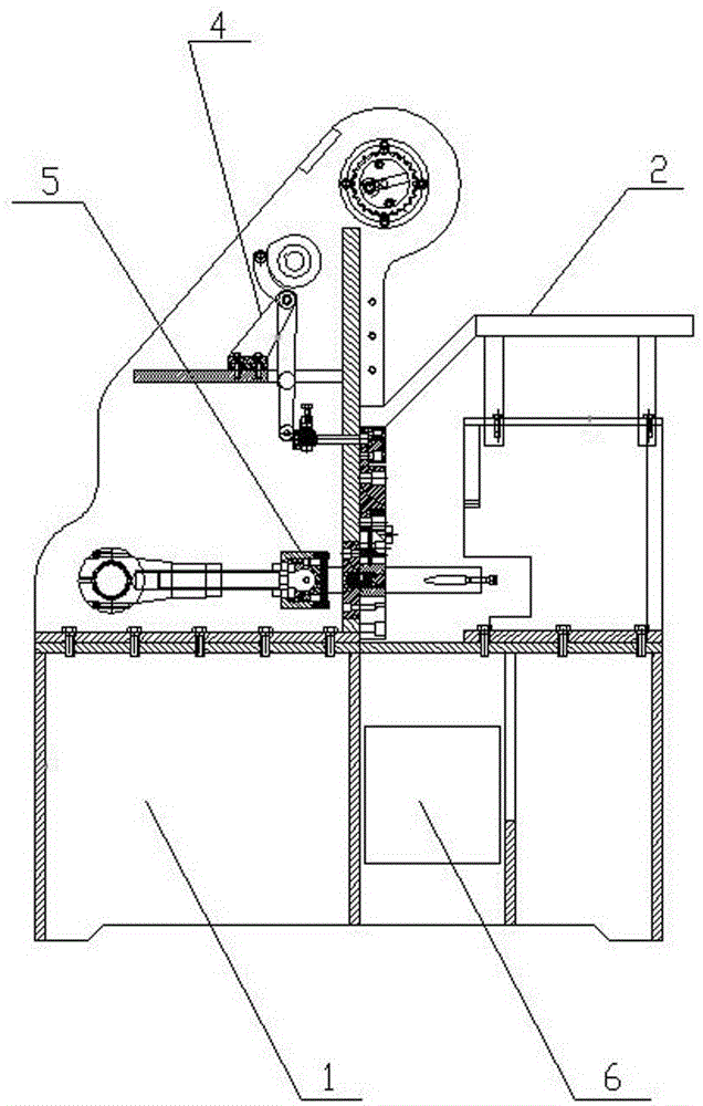
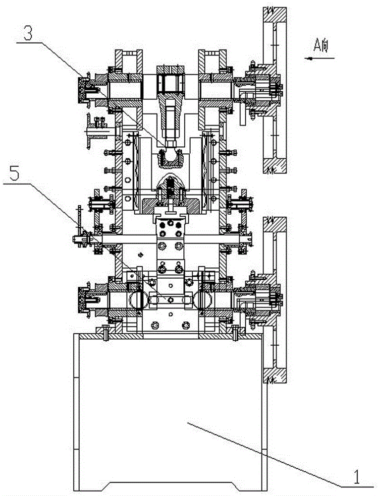
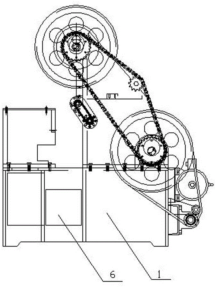
[0029] A double-hook stirrup automatic forming machine, comprising a frame 1 and a driving device arranged on the frame 1, a blanking device 2, a bending device 3, a pushing device 4 and a hook device 5, the bending device 3 , pusher device 4 and crotch device 5 are all driven by the driving device to complete the operation, and a material receiving box 6 is also provided below the crotch device 5 on the frame 1, and the end of the unloading device 2 is connected with the bending The station slot of the device 3 is docked, and the long steel bar 7 transported from the unloading device 2 to the station slot is punched downward by the bending device 3 into a U-shaped structure, and the U-shaped structural steel bar 7 is then fed by the pushing device 4 Push down from the station slot of the bending device 3 to the station slot of the hook device 5, and aft...


PUM


Abstract

An automatic forming machine for double-hook hoops comprises a machine frame, a drive device arranged on the machine frame, a feeding device, a bending device, a material pushing device and a hook device, wherein the feeding device, the bending device, the material pushing device and the hook device are arranged on the machine frame and driven by the drive device. A receiving box is arranged below the hook device on the machine frame, the tail end of the feeding device is in butt joint with a station groove of the bending device, a long-strip-shaped steel bar which is conveyed into the station groove from the feeding device is punched downwards by the bending device to form a U-shaped structure, the steel bar of the U-shaped structure is then pushed by the material pushing device into a station groove of the hook device from the station groove of the bending device, and after the two ends of the steel bar of the U-shaped structure are bent to form hooked structures through the hook device, the steel bar automatically falls into the receiving box, so that automatic double-hook hooping work for the steel bar is completed. According to the automatic forming machine for the double-hook hoops, punching shearing force can be used for completing multiple machining processes from the long-strip-shaped steel bar to the final hook product at a time, the processes are simple, the automation degree is high, and the hook effect is good. Production efficiency is improved.

Description

technical field [0001] The invention relates to the technical field of construction engineering machinery and equipment, in particular to an automatic stirrup forming machine that can continuously and automatically bend elongated steel bars into U-shaped steel bars with double-hook structures at both ends. Background technique [0002] With the extensive use of concrete in the construction field, in order to meet the shear strength of oblique sections, various steel bending structures are required in concrete structures. Generally speaking, stirrups are divided into single-leg stirrups, open rectangular stirrups, and closed rectangular stirrups. , rhombus stirrups, polygonal stirrups, well-shaped stirrups and circular stirrups, etc. In addition, in order to strengthen the bonding force between the steel bar and the concrete, the end of the stressed bar should be provided with a hook when it is a smooth round bar. With the development of technology, the bending process has b...

Claims


Application Information

Patent Timeline
Patent Type & Authority Patents(China)
IPC IPC(8): B21D11/12B21F1/00B21F1/06B21F23/00
CPCB21D11/12B21F1/00B21F1/06B21F23/005
Inventor 周光辉孙亚宾李向锋
Owner RUZHOU ZHENGTIE SANJIA CEMENT PROD
Why Eureka
Try Eureka