Electric soldering iron with conveying mechanism

A technology of feeding mechanism and electric soldering iron, which is applied in the direction of soldering iron, tin feeding device, metal processing equipment, etc. It can solve problems such as inaccurate positioning, falling off, excessive solder joints, etc., and achieve the effect of preventing uneven tin output

Inactive Publication Date: 2015-03-25
CHONGQING KUGEER ELECTRONICS
View PDF0 Cites 2 Cited by
  • Summary
  • Abstract
  • Description
  • Claims
  • Application Information

AI Technical Summary

Problems solved by technology

When operating, the soldering iron tip must first touch the independently placed solder, which is a brazing wire with a flux core, so that a small section of the soldering wire is heated and melted and adhered to the surface of the soldering iron, and then the soldering iron tip can be moved to the end of the workpiece for welding. Let the liquid solder adhering to the sold

Method used


Image

  • Electric soldering iron with conveying mechanism
  • Electric soldering iron with conveying mechanism

Examples


Embodiment Construction

[0013] The present invention will be further described in detail below in conjunction with the accompanying drawings by means of specific embodiments:

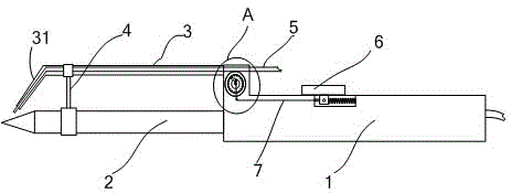
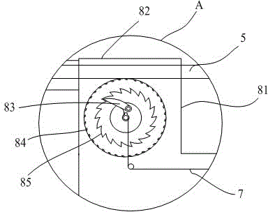
[0014] like figure 1 and figure 2 As shown, the electric soldering iron with a feeding mechanism includes an electric soldering iron composed of a handle 1, a heating wire tube and a soldering iron rod 2. A spring switch 6 is provided on the handle 1, and a ratchet feeder is provided at the junction of the handle 1 and the soldering iron rod 2. The ratchet feeder includes a feeding tube 3, a feeding ratchet and a housing 81. The feeding ratchet arranged in the housing 81 is an internal meshing ratchet and includes a ratchet claw 83 and an outer ring 85. The rotation center of the ratchet claw 83 is connected to the handle 1 by a coil spring. The edge of the ring 85 is provided with feeding teeth 84 inclined to one end of the soldering iron rod. The upper surface of the shell 81 is an arc-shaped half-pipe 82, and a tin wire w...


PUM


Abstract

The invention relates to the field of electric element welding auxiliary equipment, in particular to an electric soldering iron with a conveying mechanism. The electric soldering iron comprises an electric soldering iron body, wherein the electric soldering iron body consists of a handle, an electric heating wire pipe and a soldering iron rod, a spring switch is arranged on the handle, a ratchet conveyer is arranged at the joint of the handle and the soldering iron rod, the ratchet conveyer comprises a conveying pipe, a conveying ratchet and a casing, the conveying ratchet arranged in the casing is an internal engagement ratchet comprising a ratchet pawl and an outer ring, the rotating center of the ratchet pawl is connected to the handle through a coiled spring, conveying teeth inclining towards one end of the soldering iron rod are arranged on the edge of the outer ring, an arc-shaped half-pipe is arranged on the upper surface of the casing, a tin wire threading channel is formed between the outer ring and the arc-shaped half-pipe, the conveying pipe is concentric with the arc-shaped half-pipe and extends to the end part of the soldering iron rod, and the spring switch is connected with the ratchet pawl through a pull rod. The electric soldering iron has the benefits that the conveying purpose can be achieved as long as the spring switch is pushed, and tin can be replenished only through right-hand operation.

Description

technical field [0001] The invention belongs to the field of electric component welding auxiliary equipment, in particular to an electric soldering iron with a feeding mechanism. Background technique [0002] In the electronic industry, the use of electric soldering iron is very extensive, and existing electric soldering iron has a heating tube with built-in heating wire, and its top is connected with handle. Its lower part is connected with a detachable soldering iron tip. After power on, the heating tube can heat the tip of the soldering iron to a certain temperature. When operating, the soldering iron tip must first touch the independently placed solder, which is a brazing wire with a flux core, so that a small section of the soldering wire is heated and melted and adhered to the surface of the soldering iron, and then the soldering iron tip can be moved to the end of the workpiece for welding. Let the liquid solder adhering to the soldering iron be transferred to the w...

Claims


Application Information

Patent Timeline
IPC IPC(8): B23K3/03B23K3/06
CPCB23K3/0338B23K3/063
Inventor 谭华强
Owner CHONGQING KUGEER ELECTRONICS
Why Eureka
Try Eureka