
Automatic foot pad pressing machine

An automatic pad machine technology, applied in metal processing, metal processing equipment, manufacturing tools, etc., can solve the problems of difficult product quality assurance, low production efficiency, high labor intensity, etc., to avoid non-pressing The effect of good or damaged products, high production efficiency, and low labor intensity

Active Publication Date: 2015-03-25
SHENZHEN GONGJIN ELECTRONICS CO LTD
View PDF7 Cites 7 Cited by
  • Summary
  • Abstract
  • Description
  • Claims
  • Application Information

AI Technical Summary

Problems solved by technology

[0003] The purpose of the present invention is to provide an automatic foot pad presser, which aims to solve the problems of high labor intensity, low production efficiency, the pressing effect of the foot pad and the product quality caused by directly pressing the foot pad into the electronic product in the prior art. The quality is difficult to ensure the consistency of the problem

Method used


Image

  • Automatic foot pad pressing machine
  • Automatic foot pad pressing machine
  • Automatic foot pad pressing machine

Examples


Embodiment Construction

[0026] In order to make the object, technical solution and advantages of the present invention clearer, the present invention will be further described in detail below in conjunction with the accompanying drawings and embodiments. It should be understood that the specific embodiments described here are only used to explain the present invention, not to limit the present invention.

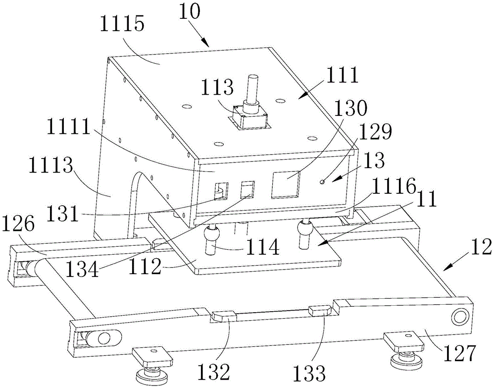
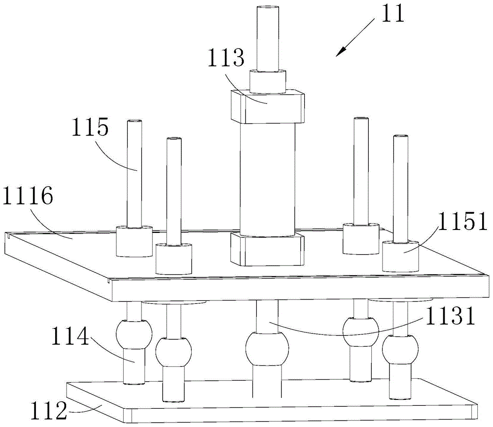
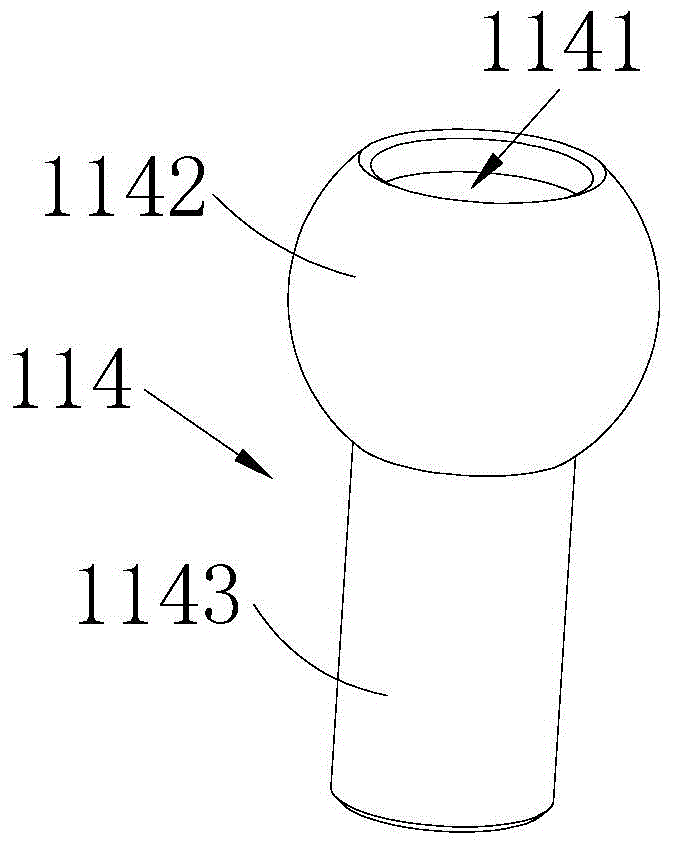
[0027] Such as Figure 1-9 Shown is the preferred embodiment provided by the present invention.

[0028] It should be noted that, when an element is referred to as being “fixed on” or “disposed on” another element, it may be directly on the other element or there may be an intervening element at the same time. When an element is referred to as being "connected to" another element, it can be directly connected to the other element or intervening elements may also be present.

[0029] It should also be noted that the orientation terms such as left, right, up, and down in this embodiment are only re...


PUM


Abstract

The invention relates to the technical field of electronic product production equipment, and provides an automatic foot pad pressing machine. The automatic foot pad pressing machine comprises a pressing mechanism, a conveying mechanism and an electronic control module. The pressing mechanism comprises a support. A pressing plate and a driving component are arranged on the support. Guide rods are arranged on the support. The guide rods are connected with the pressing plate through knuckle bearings respectively. The knuckle bearings are sleeved with balance pressure springs. The conveying mechanism is adopted to convey foot pads to the position below the pressing plate, and the driving component drives the pressing plate to press the foot pads downwards under the control of the electronic control module. The balance pressure springs can automatically adjust deformation to adapt to the different foot pads whether the surfaces of the foot pads are planes or inclined faces. In this way, the automatic food pad pressing machine is simple in structure, easy to operate, convenient to maintain, stable in work, high in reliability, small in labor intensity and high in production efficiency, and the pressing-in effect of the foot pads and the product quality are ensured.

Description

technical field [0001] The invention belongs to the technical field of electronic product presser pad machine production equipment, and in particular relates to an automatic foot presser pad machine. Background technique [0002] At present, in the process of pressing the foot pads of electronic products, the existing presser pad machines generally press the foot pads into electronic products manually by hand. If there are many foot pads in electronic products, it will cause the entire The labor intensity of the pressing process is high, resulting in low production efficiency, and because the foot pads are directly pressed into the electronic product manually, the pressure during the pressing cannot be well controlled during the pressing process. There will also be cases where the product is not pressed well due to insufficient pressure, or the product may be damaged due to excessive pressure. Therefore, it is difficult to ensure the consistency of the pressing effect of the...

Claims


Application Information

Patent Timeline
Patent Type & Authority Applications(China)
IPC IPC(8): B23P19/02
CPCB23P19/001B23P19/027
Inventor 顾正漆建中武正旭温万星岑忠孝李文峰刘露曹亮姚伟谢卓
Owner SHENZHEN GONGJIN ELECTRONICS CO LTD
Learn More