
RFID radio frequency license plate with communication function

A license plate and radio frequency technology, applied in the field of RFID radio frequency license plate, can solve the problems of difficult road sub-lane identification, no sub-lane identification to detect vehicle violations, and high cost, and achieve the effect of improving read and write sensitivity.

Active Publication Date: 2015-03-25
SHENZHEN JG TECH IND
View PDF6 Cites 38 Cited by
  • Summary
  • Abstract
  • Description
  • Claims
  • Application Information

AI Technical Summary

Problems solved by technology

[0002] At present, the existing RFID radio frequency signs and RFID radio frequency license plates use passive radio frequency chips and graphic planar antennas, which have low reading sensitivity and are difficult to apply to road lane identification. Except for ETC automatic toll collection, there is no radio frequency for lane identification and detection of vehicle violations. Applications and Reports
[0003] Moreover, the RFID radio frequency signs and RFID radio frequency license plates of the current prior art use passive radio frequency chips, and their chip memory is less than 1kbt, which cannot meet the needs of large information exchanges such as road management, road tolls, and parking lot charges.
[0004] The ETC expressway toll system of the prior art uses 5.8G active radio frequency card, which is not only costly, but also unable to let car owners or drivers know the results of radio frequency identification in time: the amount of toll deduction and deposit balance, and it cannot be applied to traffic violation detection
[0005] In addition, the "signage with RFID communication function" of the prior art uses a radio frequency tag background reader to read the information of the signage chip, and the radio frequency background reader increases the structure and cost of the radio frequency license plate, which affects the mass promotion and application of radio frequency license plates

Method used


Image

  • RFID radio frequency license plate with communication function
  • RFID radio frequency license plate with communication function
  • RFID radio frequency license plate with communication function

Examples


Embodiment Construction

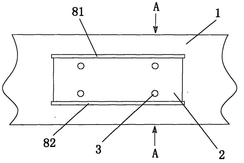
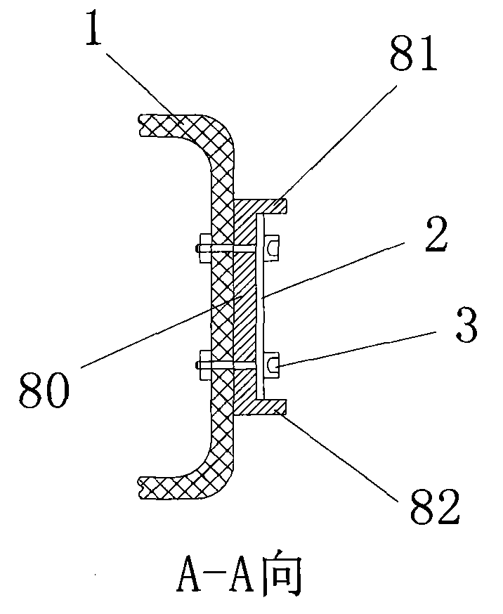
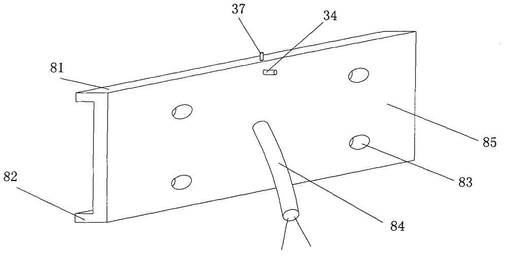
[0071] Such as Figure 1-5 As shown, an RFID radio frequency license plate with communication function is characterized in that it includes a license plate housing 80. The license plate housing 80 is provided with seven components: an active radio frequency chip 20, a half-wave oscillator antenna 10 and a nearby Field antenna 11, anti-disassembly radio frequency chip self-destruction device 30, data processor 40, vibration sensor 50, voltage adjustment and power failure alarm device 60, GPRS wireless communication module assembly 70:

[0072] The active radio frequency chip 20 is externally connected to the half-wave oscillator antenna 10 and the near-field antenna 11. The active radio frequency chip 20 is divided into six areas: the EPC area as the basic information area of ​​the vehicle, and the area as the detailed information area of ​​the vehicle. In area T, the basic vehicle information area and the detailed vehicle information area are both non-rewriteable areas and are wr...


PUM


Abstract

The invention discloses an RFID radio frequency license plate with a communication function. The RFID radio frequency license plate is characterized in that the license plate comprises a license plate shell, the license plate shell is internally provided with an active radio frequency chip, a half-wave dipole antenna and a near-field antenna, an anti-dismantling radio frequency chip self-destruction device, a data processor, a vibration sensor, a voltage regulation and outage alarm device and a GPRS wireless communication module assembly. The RFID radio frequency license plate can assist in building a dynamic vehicle positioning database and determining positions of all vehicles on highways and is used for inquiring for the positions of lost vehicles and fake-licensed vehicles and inquiring for the position of a certain vehicle, the social security management level is increased, the radio frequency license plate serves as an information carrier and a communication media, and a big data vehicle networking related to related vehicle highway departments, drivers and vehicle owner units is built.

Description

【Technical Field】 [0001] The invention relates to an RFID radio frequency license plate with communication function. The invention belongs to the application of RFID radio frequency technology in the field of vehicle and traffic management. 【Background technique】 [0002] At present, the existing RFID radio frequency signs and RFID radio frequency license plates use passive radio frequency chips and graphic planar antennas, which have low reading sensitivity and are difficult to apply to highway lane identification. Except for ETC automatic toll collection, there is no lane identification and detection of vehicle violation radio frequency. Applications and reports. [0003] Moreover, the current RFID radio frequency signs and RFID radio frequency license plates of the existing technology use passive radio frequency chips, and their chip memory is less than 1kbt, which cannot meet the needs of large information exchanges such as highway management, highway toll collection, and parki...

Claims


Application Information

Patent Timeline
IPC IPC(8): B60R13/10G06K19/077G06K17/00G07B15/06
CPCG06K19/077B60R13/10G07B15/06G08G1/017B60R13/105G06K17/00
Inventor 焦林
Owner SHENZHEN JG TECH IND
Learn More