Foot wheel type robot leg structure and foot wheel type robot with same

A robot and wheel-foot technology, applied in the field of robots, can solve the problems of insufficient walking stability, difficulty in adapting to complex terrain, and poor cushioning performance, and achieve the effects of easy deformation, strong adaptability and good cushioning performance.

Inactive Publication Date: 2015-03-25
SHANDONG UNIV
View PDF6 Cites 33 Cited by
  • Summary
  • Abstract
  • Description
  • Claims
  • Application Information

AI Technical Summary

Problems solved by technology

The patent application has poor cushioning performance, insuffi...

Method used


Image

  • Foot wheel type robot leg structure and foot wheel type robot with same
  • Foot wheel type robot leg structure and foot wheel type robot with same
  • Foot wheel type robot leg structure and foot wheel type robot with same

Examples


Embodiment 1

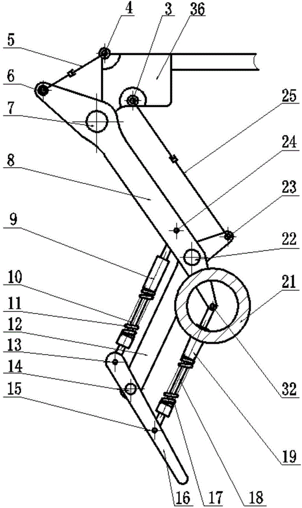
[0037] Embodiment 1: a kind of robot leg structure, its structure is as figure 1 , Figure 4 shown, including:

[0038] Body shoulder 36, the body shoulder 36 has a first hinge node, pin shaft 7 is arranged in the first hinge node, the upper side of the first hinge node is a second hinge node, pin shaft 4 is arranged in the second hinge node , the right side of the first hinge node is the third hinge node, and the pin shaft 3 is arranged inside the third hinge node;

[0039] The upper end of the thigh rod 8 is hinged with the body shoulder 36 through the pin shaft 7, the top of the thigh rod 8 is hinged with the hip joint hydraulic cylinder 5 through the pin shaft 6, and the other end of the hip joint hydraulic cylinder 5 is connected with the body shoulder through the pin shaft 4. Part 36 is hinged;

[0040] The lower end of the thigh rod 8 is hinged with the upper end of the calf rod 12 through the pin shaft 22, the top of the calf rod 12 is hinged with the knee joint hyd...

Embodiment 2

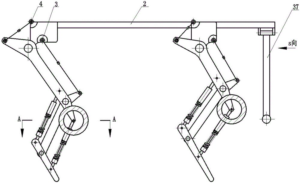
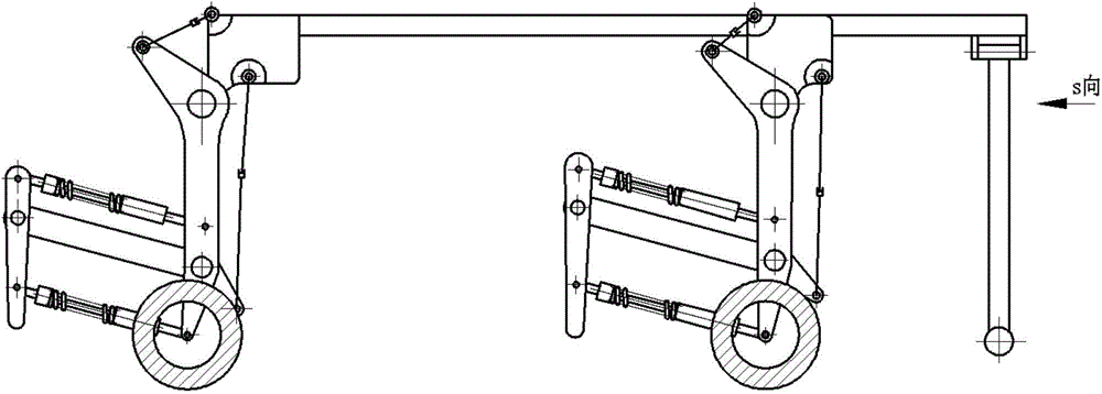
[0050] Such as Figure 1-5 As shown, the present invention also provides a wheel-foot robot, which has a body 2 on which four robot leg structures described in Embodiment 1 are installed. The body shoulders 36 are welded to the body 2 .

[0051] The front end of the robot is provided with an obstacle removal unit. Specifically, the wrecker unit includes a left side wrecker bar 37 and a right side wrecker bar 38 hinged to the body 2, and the left side wrecker bar 37 is also hinged to the left side wrecker bar hydraulic cylinder 34 , the other end of the left wrecker hydraulic cylinder 34 is hinged with the body 2; the right wrecker 38 is also hinged with the right hydraulic cylinder 33, and the other end of the right hydraulic cylinder 33 It is also hinged with the body 2; and the bottom ends of the left side wrecker bar 37 and the right side wrecker bar 38 are all provided with a wrecker block 35 .

[0052] continue to refer figure 1 and figure 2 As shown, under uneven r...


PUM


Abstract

The invention relates to a foot wheel type robot leg structure. The foot wheel type robot leg structure comprises a thigh with the top connected with a first power mechanism, and the lower side of the top is hinged to an external member to form a hip joint; a wheel, a second power mechanism driving the wheel to rotate and a first elastic suspension unit hinged to a metatarsus rod are further arranged on the upper portion of the tail end of the thigh; the upper portion of the tail end of the thigh is hinged to the upper half of the calf to form a knee joint; the upper end of the calf is connected with a third power mechanism while the lower end is hinged to the metatarsus rod to form an ankle joint; the first elastic suspension unit comprises a sleeve and a sliding shaft respectively hinged to the thigh and the metatarsus rod, the upper end of the sliding shaft extends into the sleeve to slide in a reciprocating manner, an elastic part sleeves the sliding shaft, and the lower end of the elastic part is fixed on a boss on the lower half of the sliding shaft while the upper end of the same is fixed on the sleeve. The invention further discloses a foot wheel type robot. By the arrangement, foot type and wheel type walking modes can be realized.

Description

technical field [0001] The invention relates to the field of robots, in particular to a wheel-foot robot leg structure and a wheel-foot robot with the leg structure. Background technique [0002] At present, quadruped robots in legged robots have strong mobility and strong load capacity, and can walk on complex terrains. They have potential application prospects in military transportation, mining and other fields, but their speed is slow and their walking stability needs to be improved. Wheeled robots are suitable for flat ground and have high speed, but it is difficult to move on complex terrain. [0003] Therefore, how to design a robot with a new structure so that it can walk on different roads faster is a problem that those skilled in the art need to solve urgently. [0004] Chinese patent application CN 104029745 A discloses a leg-wheel hybrid hydraulic mechanical leg, including a thigh hydraulic cylinder, a calf hydraulic cylinder, a thigh rod plate, a calf rod plate,...

Claims


Application Information

Patent Timeline
IPC IPC(8): B62D57/028
CPCB62D57/028
Inventor 马宗利张培强朱彦防刘永超王建明
Owner SHANDONG UNIV
Why Eureka
Try Eureka