Star sensor mounting structure for thermal deformation isolation and control

A star sensor and installation structure technology, applied in the direction of aerospace vehicle guidance devices, etc., can solve the problems of large satellite attitude control error, affecting satellite in-orbit performance, and no good solution, so as to ensure relative accuracy and good power The effect of small chemical properties and dynamic response

Active Publication Date: 2015-03-25
SHANGHAI SATELLITE ENG INST
View PDF4 Cites 14 Cited by
  • Summary
  • Abstract
  • Description
  • Claims
  • Application Information

AI Technical Summary

Problems solved by technology

When the satellite is in orbit, under the action of temperature load, in addition to the thermal deformation of the star sensor installation platform itself, the thermal stress caused by the temperature difference between the star sensor installation platform and the adjacent connection structure, the thermal deformation of the adjacent structure through the force exerted by the connection etc. will also cause the pointing of the star sensor to change, resulting in a large error in the attitude control of the satellite, thus affecting the on-orbit performance of the satellite
With the development of high-resolution satellites, more and more attention is paid to the pointing control of star sensors under extreme temperature load conditions in space, but there is no good solution at present, which cannot meet the needs of future high-resolution satellite development
[0004] The problem caused by the current installation scheme of the star sensor is that the star sensor is directly connected to the frame of the star body. When the satellite frame body is deformed under the extreme temperature load in space, the direction of the star sensor will be greatly changed. changes, unable to meet the needs of high-precision satellite attitude control

Method used


Image

  • Star sensor mounting structure for thermal deformation isolation and control
  • Star sensor mounting structure for thermal deformation isolation and control
  • Star sensor mounting structure for thermal deformation isolation and control

Examples


Embodiment Construction

[0049] The present invention will be described in detail below in conjunction with specific embodiments. The following examples will help those skilled in the art to further understand the present invention, but do not limit the present invention in any form. It should be noted that those skilled in the art can make several modifications and improvements without departing from the concept of the present invention. These all belong to the protection scope of the present invention.

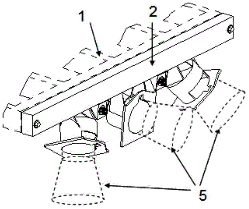
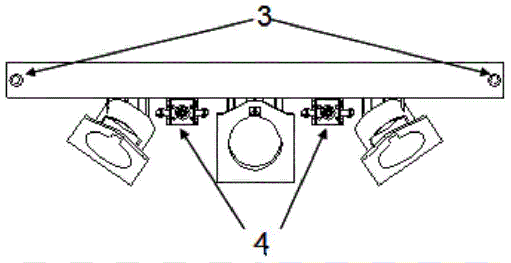
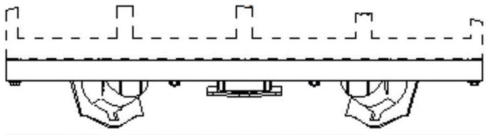
[0050] Such as figure 1As shown, this embodiment includes: a satellite body frame structure 1 , a star sensor installation beam assembly 2 , a connecting screw assembly 3 , a connecting and separating assembly 4 and a star sensor 5 . Wherein, the satellite body frame structure 1 provides threaded holes required for star sensor installation components. The star sensor installation beam assembly 2 is connected to the satellite body frame structure 1 at its two ends through the connecting screw asse...


PUM


Abstract

The invention provides a star sensor mounting structure for thermal deformation isolation and control. The star sensor mounting structure comprises a star sensor mounting cross beam assembly, connecting screw rod assemblies and connecting and separating assemblies. The two ends of the star sensor mounting cross beam assembly are connected with a star body framework through the connecting screw rod assemblies so as to release the freedom degree of rotating around the axes of screw rods at the connecting positions, by the adoption of the half-rigid connecting mode, when thermal deformation happens to the star body framework in a space extreme temperature environment, the shape of a star sensor mounting cross beam is kept unchanged, and thus it is guaranteed that the orientation of a star sensor mounted on the star sensor mounting cross beam cannot be changed. The connecting and separating assemblies play the effect of lowering the dynamic response of the star sensor under the mechanical environment excitation of a satellite launching section. After a satellite enters an orbit, added connecting points are released. The star sensor mounting structure can be used for mounting the star sensor which has a high requirement for on-orbit pointing accuracy and stability, the on-orbit thermal deformation of the star sensor mounting cross beam is isolated and controlled, and the request for utilization can be guaranteed.

Description

technical field [0001] The invention relates to a new method in the field of satellite high-precision payload installation structure design, specifically an installation scheme for isolating and controlling thermal deformation of a star sensor on orbit, especially a star sensor installation structure for thermal deformation isolation and control. Background technique [0002] With the continuous development of earth observation satellites, higher requirements are put forward for the accuracy and stability of satellite attitude control. However, the premise of improving the accuracy of attitude control is to improve the accuracy of satellite attitude measurement. The star sensor is a satellite three-axis attitude measurement device, which has the advantages of high precision and absolute measurement, and is widely used in the attitude measurement of spacecraft. [0003] During the operation of the satellite in orbit, any slight disturbance to the star sensor will affect the a...

Claims


Application Information

Patent Timeline
IPC IPC(8): B64G1/36
Inventor 彭海阔满孝颖王舒楠王志国方无迪林德贵任友良杨金军
Owner SHANGHAI SATELLITE ENG INST
Why Eureka
Try Eureka