
Parallel connection screw conveyer bin discharging conveying machine

A conveyor and screw conveyor technology, applied in the field of parallel auger out-of-warehouse conveyors, can solve problems affecting the normal process of the process, and achieve the effect of improving transmission efficiency and warehouse clearance speed

Inactive Publication Date: 2015-03-25
天津中外建输送机械有限公司
View PDF8 Cites 2 Cited by
  • Summary
  • Abstract
  • Description
  • Claims
  • Application Information

AI Technical Summary

Problems solved by technology

If the storage is rice husk, soybean meal and other oil crops with poor fluidity and easy arching, when transporting such materials, if the traditional warehouse-out equipment is equipped with electric gates, and then the warehouse-out equipment is connected, when the materials are out of the warehouse, open the electric gate Finally, soybean meal materials cannot flow out of the steel silo smoothly due to arching, which affects the normal progress of the process

Method used


Image

  • Parallel connection screw conveyer bin discharging conveying machine
  • Parallel connection screw conveyer bin discharging conveying machine

Examples


Embodiment

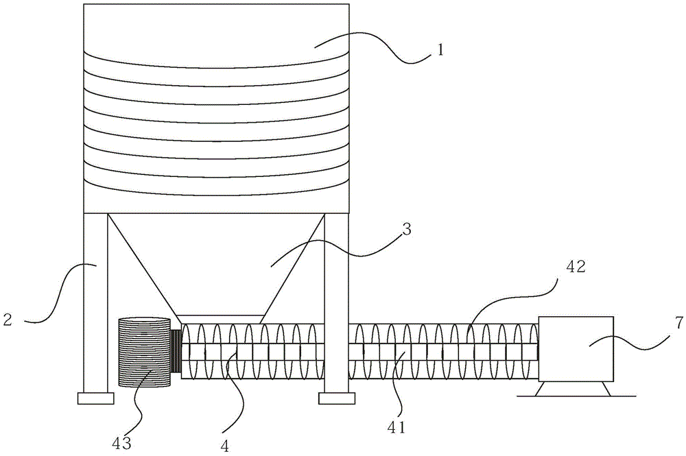
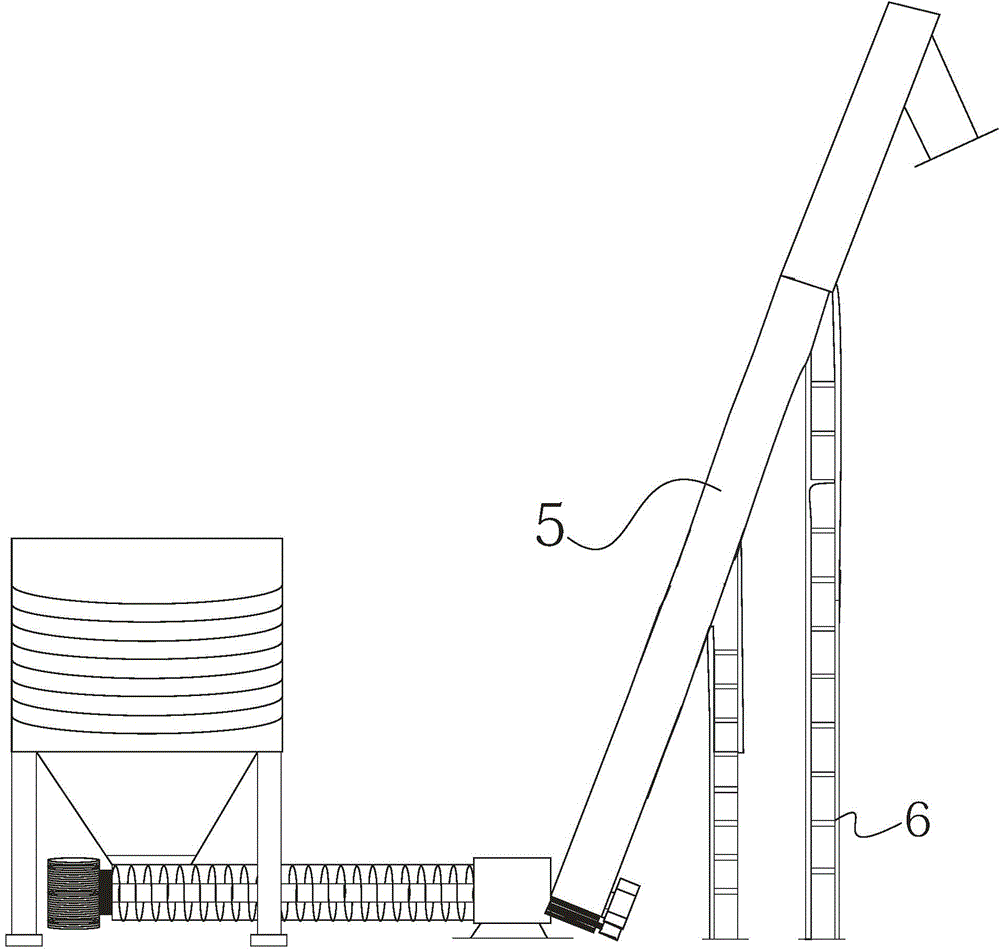
[0013] figure 1 Shown is a schematic diagram of the structure of the parallel auger discharge conveyor, the parallel auger discharge conveyor includes a storage bin 1, and a cone bucket 3 with a discharge port is arranged below the storage bin 1; the storage bin 1 A support frame 2 is arranged around the cone bucket 3; a parallel auger 4 is installed at the outlet of the cone bucket 3. The parallel auger 4 comprises at least two helical shafts 41 arranged side by side and helical blades 42 on the helical shaft. The parallel auger 4 is connected with a transmission device 43; the end of the helical shaft 41 is provided with a The bin 7; the material in the storage bin 1 directly contacts the spiral blade 42 of the parallel auger 4, and when it is out of the bin, the parallel auger 4 is directly started, and the spiral blade 42 destroys the arch of the material when it rotates, pushes the material out of the bin, and then passes through the parallel auger. The auger is transpor...


PUM


Abstract

The invention discloses a parallel connection screw conveyer bin discharging conveying machine which comprises a storage bin. A tapered hopper with a discharging opening is arranged below the storage bin. Supporting frames are arranged on the position, around the tapered hopper, of the storage bin. The discharging opening of the tapered hopper is provided with a parallel connection screw conveyer. The parallel connection screw conveyer comprises at least two screw shafts arranged side by side and screw blades on the screw shafts. The parallel connection screw conveyer is connected with a transmission device. The ends of the screw shafts are provided with a bin discharging opening. When materials are discharged out of the bin, the parallel connection screw conveyer is started directly, the screw blades rotate to destroy arch of the materials to push the materials to be discharged out of the bin, then the materials are conveyed to the bin discharging opening through the parallel connection screw conveyer, and the production requirement is guaranteed. Compared with a screw bin emptying machine, the parallel connection screw conveyer can destroy arch of the materials quickly, the conveying efficiency is improved greatly, and the bin emptying speed is increased greatly.

Description

technical field [0001] The invention relates to the technical field of screw conveying, in particular to a parallel auger discharge conveyor. Background technique [0002] Screw conveyor, commonly known as auger, is a continuous conveying equipment, mainly used for conveying powdery, granular and small block materials. The screw conveyor has the advantages of simple structure, small cross-sectional area, good sealing performance, multi-point feeding and unloading in the middle, safe and convenient operation and low manufacturing cost, so it is widely used. [0003] In order to save the warehouse-out time, the way of mechanical discharging is usually adopted, while the existing warehouse-clearing method is realized by adding a screw-clearing machine. If the storage is rice husk, soybean meal and other oil crops with poor fluidity and easy to arch, when transporting such materials, if the traditional warehouse-out equipment is equipped with electric gates, and then the wareho...

Claims


Application Information

Patent Timeline
Patent Type & Authority Applications(China)
IPC IPC(8): B65G65/46B65D88/68
CPCB65G65/46B65D88/68
Inventor 张鹏张大鹏匡小平
Owner 天津中外建输送机械有限公司
Learn More